Mitsubishi Evolution X. Manual - part 387
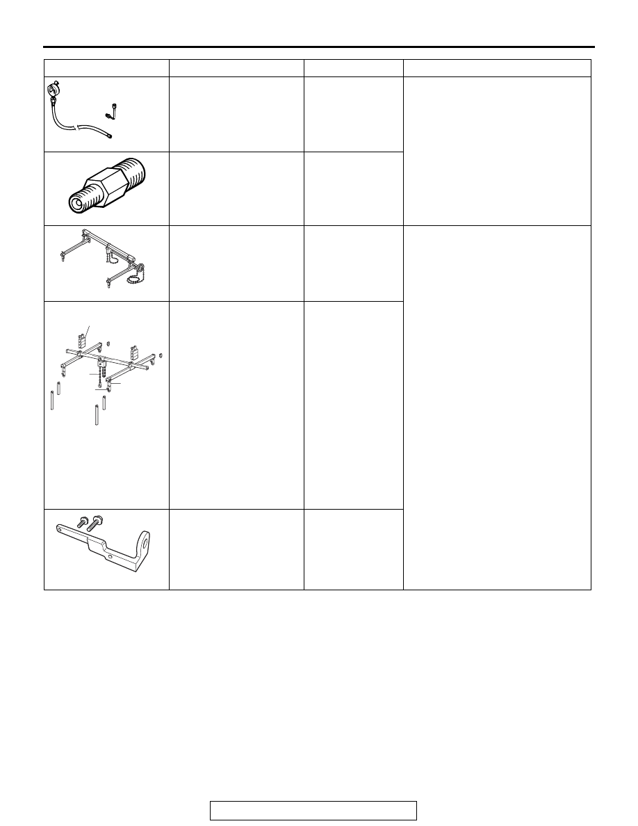
SPECIAL TOOLS
TSB Revision
TWIN CLUTCH- SPORTRONIC SHIFT TRANSMISSION (TC-SST)
22C-5
MD998330 (Includes
MD998331)
Oil pressure gauge (3.0
MPa, 427 psi)
MD998330-01
Measurement of hydraulic pressure
MB991705
Adapter
MB991895
Engine hanger
Tool not available When the engine hanger is used:
Supporting the engine assembly
during removal and installation of
the transaxle assembly
MB991928
Engine hanger
a: MB991929
Joint (50)
× 2
b: MB991930
Joint (90)
× 2
c: MB991931
Joint (140)
× 2
d: MB991932
Foot (standard)
× 4
e: MB991933
Foot (short)
× 2
f: MB991934
Chain and hook
assembly
Tool not available
MB992201
Engine hanger plate
−
Tool
Tool number and name Supersession
Application
AC103525
MB991705
MB991895
B991928
a
b
c
d
e
f
Slide Bracket (HI)
B992201