Mitsubishi Evolution X. Manual - part 346


  Index      Mitsubishi     Mitsubishi Evolution X - service repair manual 2008 year


Search            


Content   ..  344  345  346  347   ..


Mitsubishi Evolution X. Manual - part 346


DIAGNOSIS <S-AWC(SUPER ALL WHEEL CONTROL)>

TSB Revision

MANUAL TRANSAXLE

22A-33

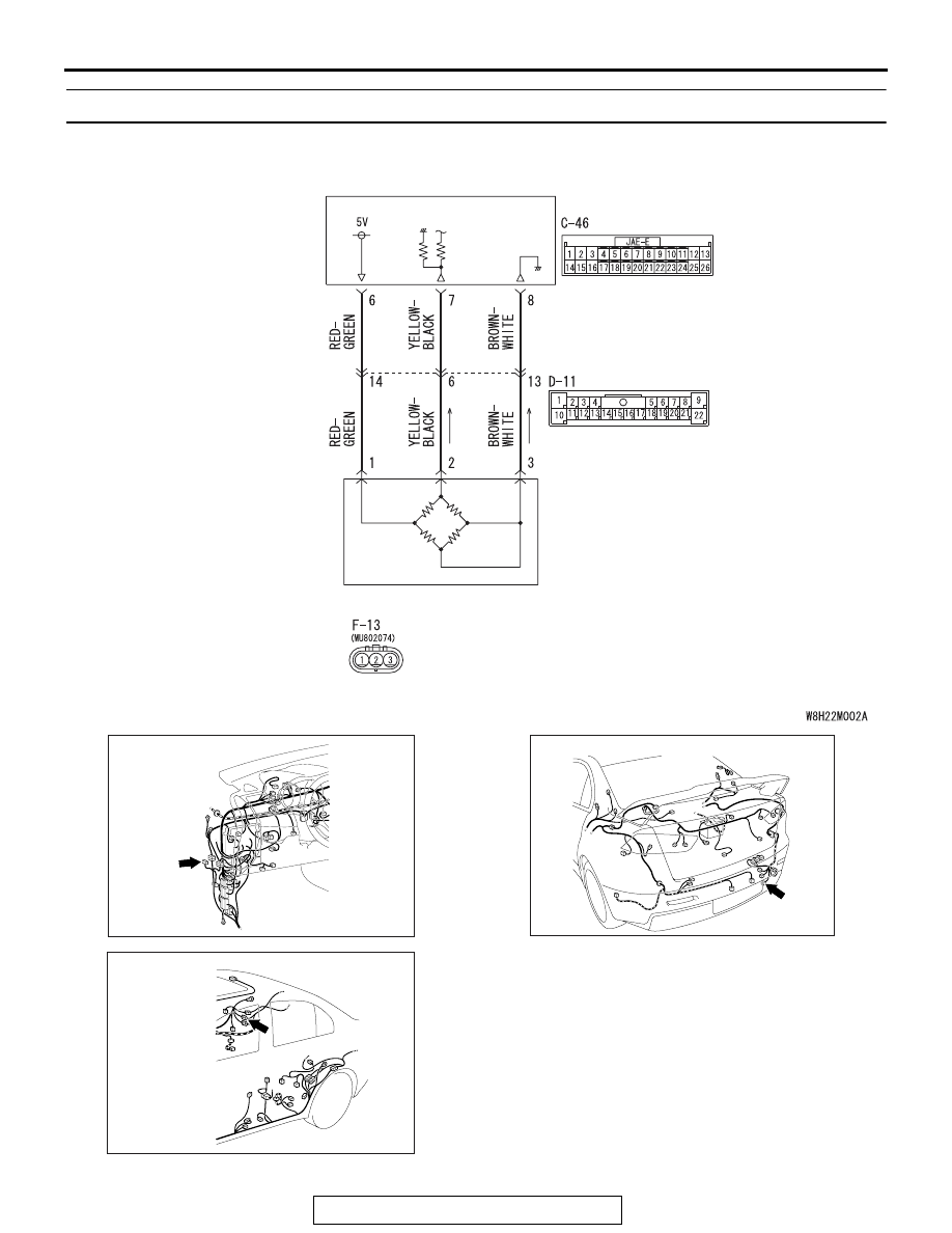
DTC C1611: AWC Pressure Sensor System (Low Voltage)

PRESSURE 
SENSOR

S-AWC-ECU

AWC pressure sensor system circuit

AC708950CG

Connector: C-46

AC708955

Connector: D-11

AO

AC708970AS

Connector: F-13

F-13 (B)

DIAGNOSIS <S-AWC(SUPER ALL WHEEL CONTROL)>

TSB Revision

MANUAL TRANSAXLE

22A-34

CAUTION

• If there is any problem in the CAN bus lines, 

an incorrect diagnostic trouble code may be 
set. Prior to this diagnosis, diagnose the CAN 
bus lines.

• Whenever the ECU is replaced, ensure that 

the CAN bus lines are normal.

.

OPERATION

AWC-ECU controls the electric pump by the informa-
tion from AWC pressure sensor.

.

DTC SET CONDITIONS

The code is set when AWC pressure sensor output 
voltage is 0.2 V or less.

.

PROBABLE CAUSES

• AWC pressure sensor malfunction

• Damaged harness wires and connectors

• Malfunction of AWC-ECU

DIAGNOSTIC PROCEDURE

STEP 1. Scan tool CAN bus diagnostics
Using scan tool MB991958, diagnose the CAN bus lines.
Q: Is the check result normal?

YES : Go to Step 3.
NO :  Repair the CAN bus lines. (Refer to GROUP 54C 

− 

Troubleshooting 

P.54C-14

.) After repairing the CAN 

bus line, go to Step 2.

STEP 2. Check whether the DTC is reset.
Q: Is DTC No. C1611 set?

YES : Go to Step 3.
NO :  This diagnosis is complete.

STEP 3. AWC-ECU connector, intermediate connector, 
AWC pressure sensor connector check: C-46, D-11, F-13
Q: Is the check result normal?

YES : Go to Step 4.
NO :  Repair the defective connector. Then go to Step 7.

STEP 4. Check the wiring harness between C-46 AWC-ECU 
connector terminal No. 7 and F-13 AWC pressure sensor 
connector terminal No. 2.
Check the wiring harness for short circuit.
Q: Is the check result normal?

YES : Go to Step 5.
NO :  Repair the wiring harness. Then go to Step 7.

STEP 5. Scan tool service data
Item No. 87: Pressure sensor output voltage (Refer to service 
data reference table 

P.22A-107

.)

Q: Is the check result normal?

YES : Go to Step 6.
NO :  Replace the hydraulic unit. (Refer to GROUP 27 

− 

Hydraulic Unit 

P.27-58

.) Then go to Step 6.

DIAGNOSIS <S-AWC(SUPER ALL WHEEL CONTROL)>

TSB Revision

MANUAL TRANSAXLE

22A-35

STEP 6. Check whether the DTC is reset.
Q: Is DTC No. C1611 set?

YES : Replace the AWC-ECU.(Refer to 

P.22A-132

.) Then, 

go to Step 7.

NO :  Intermittent malfunction. (Refer to GROUP 00 

− How 

to Cope with Intermittent Malfunction 

P.00-15

.)

STEP 7. Check whether the DTC is reset.
Q: Is DTC No. C1611 set?

YES : Return to Step 1.
NO :  This diagnosis is complete.

DTC C1612: AWC Pressure Sensor System (High Voltage)

.

AWC PRESSURE SENSOR SYSTEM 
CIRCUIT

Refer to 

P.22A-33

.

CAUTION

• If there is any problem in the CAN bus lines, 

an incorrect diagnostic trouble code may be 
set. Prior to this diagnosis, diagnose the CAN 
bus lines.

• Whenever the ECU is replaced, ensure that 

the CAN bus lines are normal.

.

OPERATION

AWC-ECU controls the electric pump by the informa-
tion from AWC pressure sensor.

.

DTC SET CONDITIONS

The code is set when AWC pressure sensor output 
voltage is 4.6 V or more.

.

PROBABLE CAUSES

• AWC pressure sensor malfunction

• Damaged harness wires and connectors

• Malfunction of AWC-ECU

DIAGNOSTIC PROCEDURE

STEP 1. Scan tool CAN bus diagnostics
Using scan tool MB991958, diagnose the CAN bus lines.
Q: Is the check result normal?

YES : Go to Step 3.
NO :  Repair the CAN bus lines. (Refer to GROUP 54C 

− 

Troubleshooting 

P.54C-14

.) After repairing the CAN 

bus line, go to Step 2.

STEP 2. Check whether the DTC is reset.
Q: Is DTC No. C1612 set?

YES : Go to Step 3.
NO :  This diagnosis is complete.

DIAGNOSIS <S-AWC(SUPER ALL WHEEL CONTROL)>

TSB Revision

MANUAL TRANSAXLE

22A-36

STEP 3. Scan tool diagnostic trouble code
Check if the AWC-related DTC No. C1625 is set.(Refer to 

P.22A-11

.)

Q: Is the DTC set?

YES : Perform the relevant troubleshooting. Then go to Step 

9.

NO :  Go to Step 4.

STEP 4. AWC-ECU connector, intermediate connector, 
AWC pressure sensor connector check: C-46, D-11, F-13
Q: Is the check result normal?

YES : Go to Step 5.
NO :  Repair the defective connector. Then go to Step 9.

STEP 5. Check the wiring harness between C-46 AWC-ECU 
connector terminal No. 7 and F-13 AWC pressure sensor 
connector terminal No. 2.
Check the wiring harness for open or short circuit (short to 
power supply).
Q: Is the check result normal?

YES : Go to Step 6.
NO :  Repair the wiring harness. Then go to Step 9.

STEP 6. Check the wiring harness between C-46 AWC-ECU 
connector terminal No. 8 and F-13 AWC pressure sensor 
connector terminal No. 3.
Check the wiring harness for open circuit.
Q: Is the check result normal?

YES : Go to Step 7.
NO :  Check D-11 intermediate connector. When no 

problem is found, repair the wiring harness. Then go 
to Step 9.

STEP 7. Scan tool service data
Item No. 87: Pressure sensor output voltage (Refer to service 
data reference table 

P.22A-107

.)

Q: Is the check result normal?

YES : Go to Step 8.
NO :  Replace the hydraulic unit. (Refer to GROUP 27 

− 

Hydraulic Unit 

P.27-58

.) Then go to Step 8.

STEP 8. Check whether the DTC is reset.
Q: Is DTC No. C1612 set?

YES : Replace the AWC-ECU.(Refer to 

P.22A-132

.) Then 

go to Step 9.

NO :  Intermittent malfunction. (Refer to GROUP 00 

− How 

to Cope with Intermittent Malfunction 

P.00-15

.)


Content   ..  344  345  346  347   ..