Mitsubishi Evolution X. Manual - part 324
MAINTENANCE SERVICE
TSB Revision
GENERAL
00-71
13. TRANSFER OIL (CHECK OIL LEVEL/CHANGE)
M1001003000208
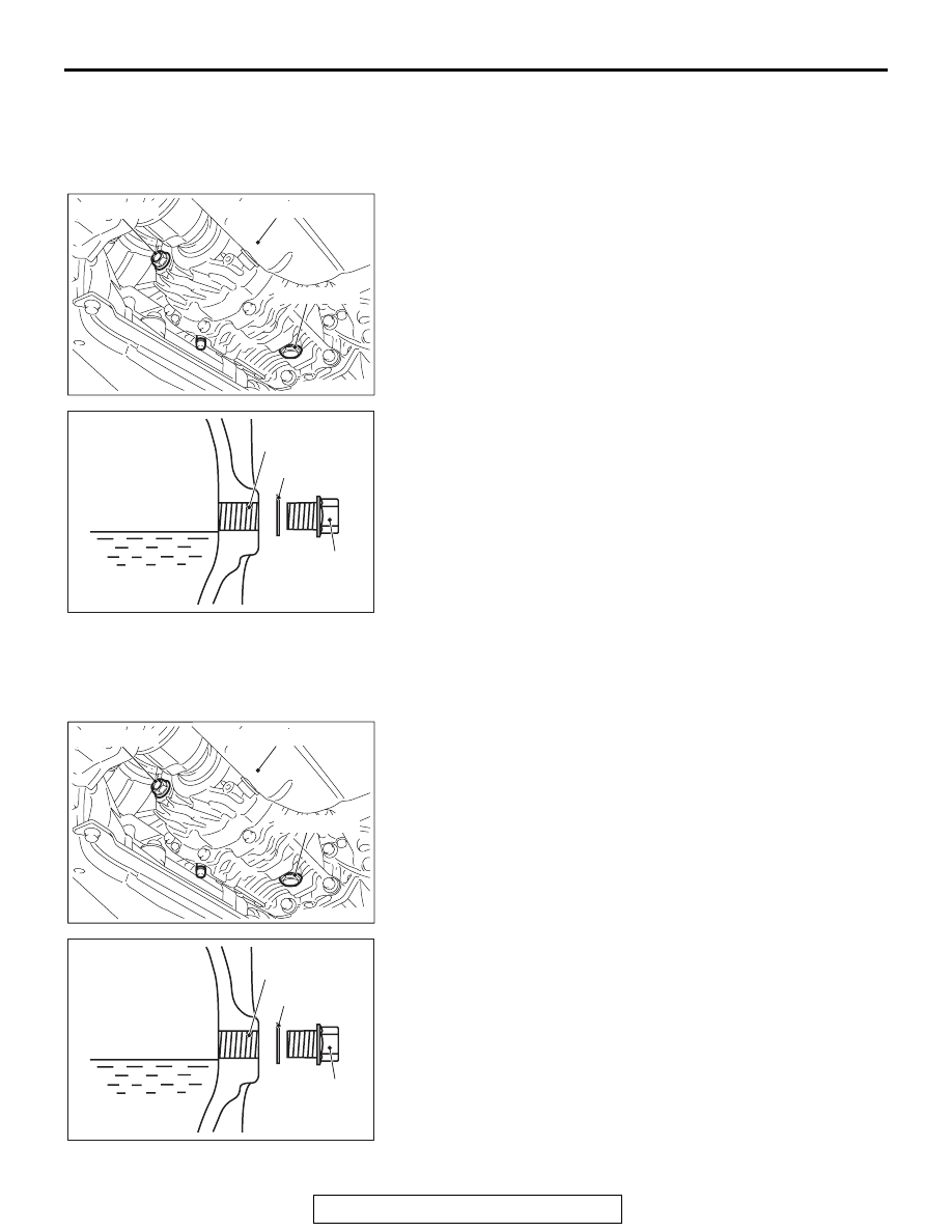
TRANSFER OIL CHECK
1. Remove the engine room under cover front B assembly.
(Refer to GROUP 51
.)
2. Remove the oil filler plug and gasket.
3. Check that the oil level is just below the lower edge of the oil
filler plug hole.
4. Check that the oil is not excessively foul and has moderate
viscosity.
5. Install the oil filler plug and new gasket, then tighten them to
the specified torque.
Tightening torque: 32
± 2 N⋅ m (24 ± 1 ft-lb)
6. Install the engine room under cover front B assembly. (Refer
to GROUP 51
− Under cover
TRANSFER OIL CHANGE
1. Remove the engine room under cover front B assembly.
(Refer to GROUP 51
.)
2. Remove the oil drain plug and gasket to drain the oil.
3. Install the oil drain plug and new gasket, then tighten them
to the specified torque.
Tightening torque: 32
± 2 N⋅ m (24 ± 1 ft-lb)
4. Remove the oil filler plug and gasket, then fill the oil up to
the lower edge of the oil filler plug hole.
Brand name: Mitsubishi genuine Dia-Queen LSD
Gear Oil
Quantity: 0.9 dm
3 (1.0 quarts)
5. Install the oil filler plug and new gasket, then tighten them to
the specified torque.
Tightening torque: 32
± 2 N⋅ m (24 ± 1 ft-lb)
6. Install the engine room under cover front B assembly. (Refer
to GROUP 51
− Under cover
AC704516AE
Oil filler plug
Oil drain plug
Engine oil pan
AC700330AE
Gasket
Transmission oil
Filler plug hole
Oil filler plug
AC704516AE
Oil filler plug
Oil drain plug
Engine oil pan
AC700330AE
Gasket
Transmission oil
Filler plug hole
Oil filler plug