Mitsubishi Evolution X. Manual - part 245
STARTING SYSTEM
TSB Revision
ENGINE ELECTRICAL
16-33
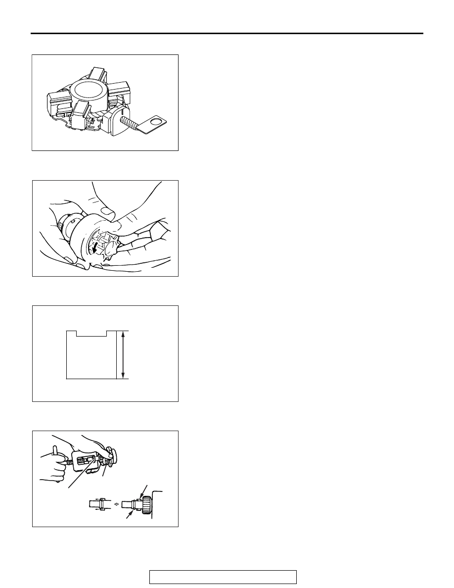
BRUSH HOLDER
AK201187
Push the brush into the brush holder to make sure that the
spring is working on the brush.
If the spring is not working, replace the brush holder.
.
OVERRUNNING CLUTCH
AK304691
Free
Lock
AG
1. Make sure that the pinion cannot be turned
counterclockwise, and can be turned clockwise freely.
2. Check the pinion for abnormal wear and damage.
.
BRUSHES
AK202846
Brush
height
AF
1. Check the commutator contacting surface of each brush for
abnormal roughness. Also check the height of the brush.
Replace the brush holder if the height is lower than the limit.
Limit: 7.0 mm (0.27 in)
2. When the contact surface of the brush is rectified or the
brush holder is replaced, recondition the contact surface
with sandpaper wrapped around the commutator.
.
ARMATURE CHECK
AK304687
Overrunning
clutch
Stop ring
Snap ring
Stop ring
AF
1. Check that the armature coil is not grounded.
2. Place the armature in a growler.
3. Hold a thin steel blade parallel and just above the armature
while slowly rotating in the growler. A shorted armature will
cause a blade to vibrate and be attracted to the core.
Replace the shorted armature.