Mitsubishi Evolution X. Manual - part 205
AK600791
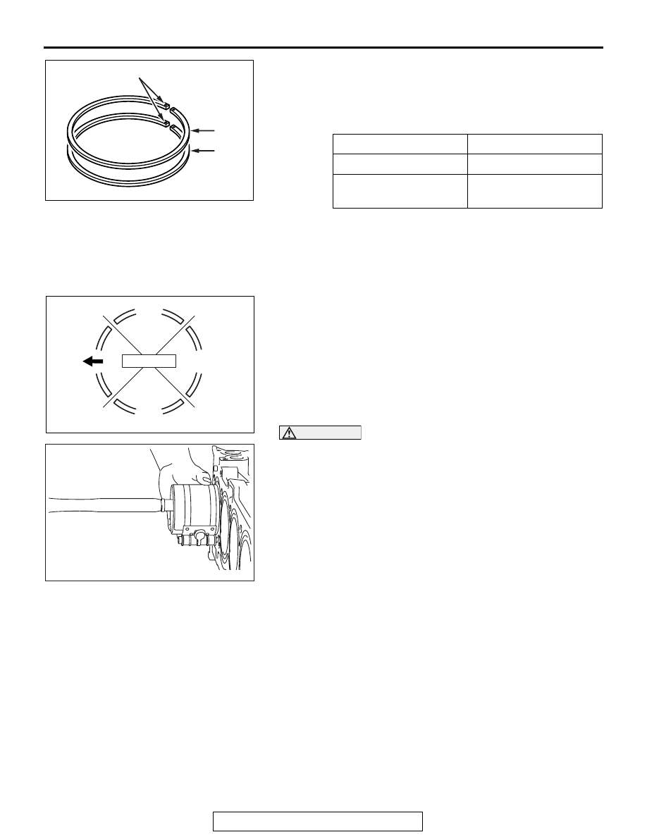
No. 2
No. 1
Identification mark
AC
PISTON AND CONNECTING ROD
TSB Revision
ENGINE OVERHAUL
11B-67
Identification mark
No. 1 ring: 1R
No. 2 ring: 2R
NOTE: Each of the available piston rings has a size mark as
follows:
Size
Size mark
Standard
No mark
0.25 mm (0.010 inch)
oversize
25
.
>>D<< PISTON CONNECTING ROD ASSEMBLY
INSTALLATION
1. Apply a sufficient amount of engine oil to the circumference
of the piston, piston rings and oil ring.
AK400403
No.1
Side rail
Side rail
AC
Piston pin
No.2
2. Arrange end gap positions of piston rings and oil ring (side
rail and spacer) as shown in the illustration.
3. Insert the piston and connecting rod assembly from the top
surface of the cylinder block with the front mark of the piston
top face facing toward the timing chain side.
AK502730
CAUTION
Driving it in hard causes breakage of piston rings and
damage to the crank pin.
4. Firmly tighten the piston ring with a ring band and insert the
piston and connecting rod assembly.
.