Mitsubishi Evolution X. Manual - part 198


  Index      Mitsubishi     Mitsubishi Evolution X - service repair manual 2008 year


Search            


Content   ..  196  197  198  199   ..


Mitsubishi Evolution X. Manual - part 198


TIMING CHAIN

TSB Revision

ENGINE OVERHAUL

11B-39

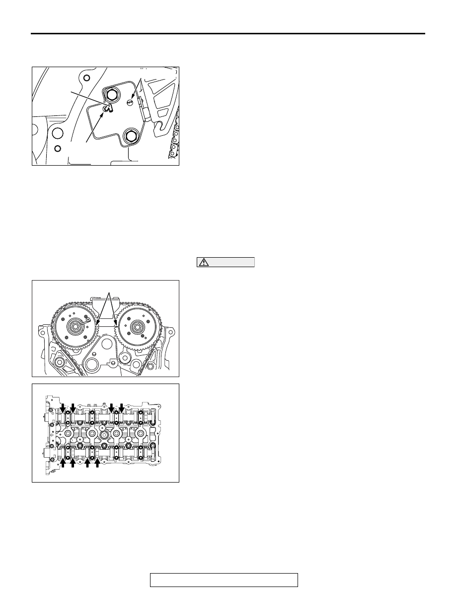
>>D<< TIMING CHAIN TENSIONER 
INSTALLATION

AK502854 AG

Wire

Ratchet release hole

Plunger fixed
hole

1. Install the timing chain tensioner on the cylinder block and 

tighten it to the specified torque.

Specified torque: 10 

± 2 N⋅ m (89 ± 17 in-lb)

2. Remove the hard wire (piano wire or the like) of 

φ1.5 or 

hexagonal bar wrench (1.5 mm [0.05 inch]) from the timing 
chain tensioner. This enables the plunger of the timing chain 
tensioner to push the tensioner lever to keep the timing 
chain tight.

INSPECTION

M1113026700462

.

VALVE CLEARANCE ADJUSTMENT

Measure valve clearance as described in the following proce-
dure.
Check and adjust the valve clearance with the timing chain 
installed.

CAUTION

Always rotate the crankshaft clockwise.

AK502968AE

Timing mark

1. Rotate the crankshaft clockwise to align the timing mark of 

the V.V.T. sprocket with the top surface of the cylinder head 
as illustrated. (Set the No. 1 piston at top dead center on the 
compression stroke.)

10

11

12

7

8

8

3

4

4

3

1

2

2

1

5

6

6

5

9

AK502387AG

Intake valve side

No.1

No.2

No.3

Exhaust valve side

No.1

2. Valve clearance can be measured at the illustrated location 

in this condition.

AK502758

TIMING CHAIN

TSB Revision

ENGINE OVERHAUL

11B-40

3. Use a thickness gauge to measure clearance between the 

camshaft and valve tappet.

Standard value (when engine is cold)

Intake side: 0.20 

± 0.03 mm (0.008 ± 0.001 inch)

Exhaust side: 0.30 

± 0.03 mm (0.012 ± 0.001 inch)

4. If measured values are out of the standard value, record 

measured values.

AK502545AG

Timing mark

5. Rotate the crankshaft by one turn clockwise to set the No. 4 

piston at top dead center on the compression stroke.
NOTE: The timing mark of the V.V.T. exhaust sprocket must 
be at the illustrated position.

10

11

12

7

8

8

3

4

4

3

1

2

2

1

5

6

6

5

9

AK502388 AF

Intake valve side

No.3

No.4

Exhaust valve side

No.2

No.4

6. Valve clearance can be measured at the illustrated location 

in this condition.

7. If measured values are out of the standard value, record 

measured values.

8. If the measured value is out of the standard value, replace 

the valve tappet.
NOTE: There are 47 kinds of valve tappets at intervals of 
0.015 mm (0.0006 inch) in the range between 3.000 (0.1181 
inch) and 3.690 mm (0.1453 inch).

AK304938

AE

Wall thickness

9. Use the following procedure select a valve tappet.

(1) Measure thickness of a removed valve tappet.
(2) Calculate thickness of a valve tappet so that valve 

clearance meets the standard value.

A: Thickness of valve tappet to be selected
B: Thickness of removed valve tappet
C: Measured valve clearance
Formula
Intake side: A = B + (C 

 0.20 mm [0.008 inch])

Exhaust side: A = B + (C 

 0.30 mm [0.012 inch])

Refer to "Removal and installation of camshaft" for removal, 
installation and inspection procedure of valve tappets.

CAMSHAFT

TSB Revision

ENGINE OVERHAUL

11B-41

CAMSHAFT

REMOVAL AND INSTALLATION

M1113026900400

AK702227

1

2

3

4

5

6

10

11

12

13

AC

7

8

7

9

6

7

8

7

10 ± 2 N·m
89 ± 17 in-lb

10 ± 2 N·m
89 ± 17 in-lb

12 ± 1 N·m
107 ± 8 in-lb

Apply engine oil to
all moving parts
before installation.

30 ± 2 N·m
22 ± 1 ft-lb

17 ± 3 N·m
14 ± 2 ft-lb 

Removal steps 

>>C<<

1. Engine oil control valve (OCV) 

exhaust

>>C<<

2. O-ring

>>C<<

3. Engine oil control valve (OCV) 

intake

>>C<<

4. O-ring

<<A>> >>B<<

5. Front camshaft bearing cap

<<A>> >>B<<

6. Oil feeding camshaft bearing cap

<<A>> >>B<<

7. Camshaft bearing cap

<<A>> >>B<<

8. Thrust camshaft bearing cap

>>B<<

9. Bearing

>>B<<

10. Camshaft intake

>>B<<

11. Camshaft exhaust
12. Bearing

<<B>> >>A<<

13. Valve tappet

Removal steps (Continued)

CAMSHAFT

TSB Revision

ENGINE OVERHAUL

11B-42

REMOVAL SERVICE POINTS

.

<<A>> FRONT CAMSHAFT BEARING CAP / OIL 
FEEDING CAMSHAFT BEARING CAP / CAM-
SHAFT BEARING CAP / THRUST CAMSHAFT 
BEARING CAP REMOVAL

AK502389AD

5

6

7

8

10

2

1

5

6

7

8

12

3

4

9

9

10

11

11

12

CAUTION

Loosing the camshaft bearing cap installation bolts in four 
to five steps. Do not loosen bolts in one step as this 
causes the valve spring force to push on the bolts and 
make them jump out causing damage to the threads.
First remove a mounting bolt of the front camshaft bearing cap 
and then a mounting bolt of each camshaft bearing cap in the 
order shown in the illustration.

.

<<B>> VALVE TAPPET REMOVAL

Pick out valve tappets with fingers and store removed valve 
tappets with tags describing the installed position attached for 
reassembly.

INSTALLATION SERVICE POINTS

.

>>A<< VALVE TAPPET INSTALLATION

Install valve tappets at the same position based on tags 
describing the installed position for reassembly.

.

>>B<< CAMSHAFT / BEARING / THRUST 
CAMSHAFT BEARING CAP / CAMSHAFT 
BEARING CAP / OIL FEEDING CAMSHAFT 
BEARING CAP / FRONT CAMSHAFT BEARING 
CAP INSTALLATION

AK502969AD

Identification 
mark

1. When replacing a camshaft bearing, select a bearing with 

the size corresponding to the identification mark in the table 
below.

2. Install camshaft bearings on the cylinder head.

Front camshaft bearing cap

Camshaft bearing

Identification 
mark

Inner diameter 
mm (in)

Identification mark

1

40.000 

− 40.008 

(1.5748 

− 1.5751)

1

2

40.008 

− 40.016 

(1.5751 

− 1.5754)

2

3

40.016 

− 40.024 

(1.5754 

− 1.5757)

3


Content   ..  196  197  198  199   ..