Content .. 1278 1279 1280 1281 ..
Mitsubishi Evolution X. Manual - part 1280
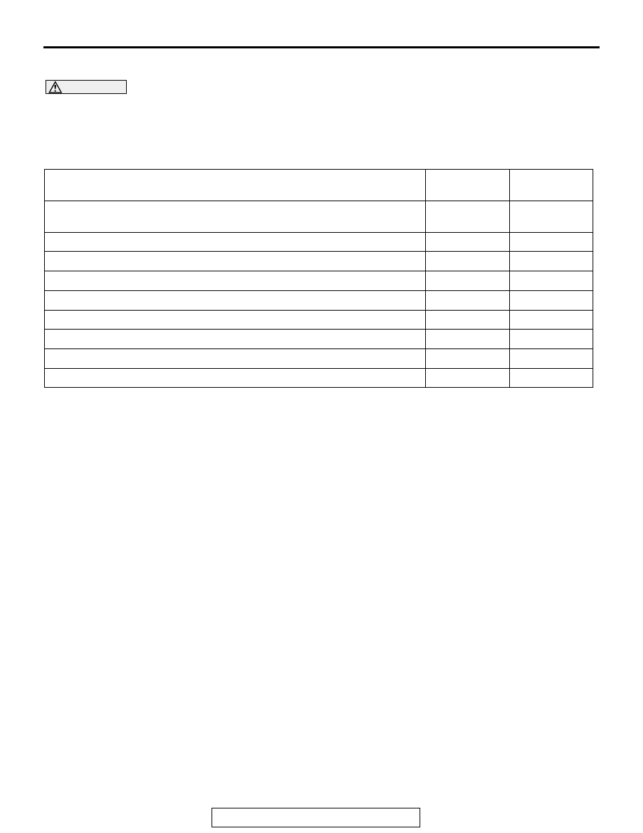
AUTO A/C DIAGNOSIS
TSB Revision
HEATER, AIR CONDITIONING AND VENTILATION
55-71
SYMPTOM CHART
M1552009900729
CAUTION
During diagnosis, a DTC code associated with
other system may be set when the ignition switch
is turned on with connector(s) disconnected. On
completion, confirm all systems for DTC code(s).
If DTC code(s) are set, erase them all.
Symptom
Inspection
procedure
Reference
page
When the A/C is operation, temperature inside the passenger
compartment does not decrease (Cool air is not emitted).
1
Malfunction of the A/C-ECU power supply system.
2
The compressor does not work.
3
Blower fan and motor do not turn.
4
Blower air amount cannot be changed.
5
Outside/inside air changeover is not possible.
6
A/C outlet air temperature does not increase.
7
Air outlet vent cannot be changed.
8
Blower motor power supply system.
9