Mitsubishi Evolution X. Manual - part 1269


  Index      Mitsubishi     Mitsubishi Evolution X - service repair manual 2008 year


Search            


Content   ..  1267  1268  1269  1270   ..


Mitsubishi Evolution X. Manual - part 1269


AUTO A/C DIAGNOSIS

TSB Revision

HEATER, AIR CONDITIONING AND VENTILATION

55-27

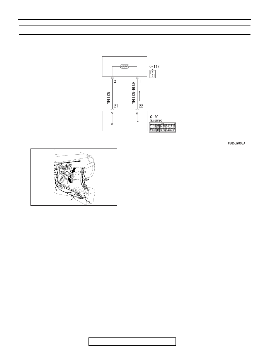
DTC B1031, B1032: Fin Thermo Sensor System

.

DTC SET CONDITION

• DTC B1031 is set if there is a short circuit in the fin thermo 

sensor input circuit.

• DTC B1032 is set if there is a defective connector connec-

tion, or if there is an open circuit in the harness.

.

TECHNICAL DESCRIPTION (COMMENT)

Current trouble

• The A/C-ECU, the fin thermo sensor, or connector(s) or wir-

ing between the two may be defective.

Past trouble

• If DTC B1031 or B1032 is stored as a past trouble, carry out 

diagnosis with particular emphasis on wiring and connec-
tor(s) between the A/C-ECU and the fin thermo sensor. If 
the connectors and wiring are normal, and obviously the 
ECU is the cause of the trouble, replace the ECU. If in 
doubt, do not replace the ECU.

.

Fin Thermo Sensor Circuit

A/C-ECU

FIN THERMO
SENSOR

AC708602

AC708951AK

C-20 (B)

Connectors: C-20, C-113

C-113

AUTO A/C DIAGNOSIS

TSB Revision

HEATER, AIR CONDITIONING AND VENTILATION

55-28

TROUBLESHOOTING HINT

• Malfunction of connector.

• Malfunction of the harness.

• Malfunction of the fin thermo sensor.

• Malfunction of the A/C-ECU.

DIAGNOSIS

Required Special Tool:

•  MB991958: Scan Tool (M.U.T.-III Sub Assembly)

• MB991824: Vehicle Communication Interface (V.C.I.)

• MB991827: M.U.T.-III USB Cable

• MB991910: M.U.T.-III Main Harness A 

STEP 1. Using scan tool MB991958, diagnose the CAN bus 
line

CAUTION

To prevent damage to scan tool MB991958, always turn the 
ignition switch to the "LOCK" (OFF) position before con-
necting or disconnecting scan tool MB991958.
(1) Connect scan tool MB991958. Refer to "How to connect the 

Scan Tool (M.U.T.-III) 

P.55-7

."

(2) Turn the ignition switch to the "ON" position.
(3) Diagnose the CAN bus line.
(4) Turn the ignition switch to the "LOCK" (OFF) position.
Q: Is the CAN bus line found to be normal?

YES : Go to Step 2.
NO :  Repair the CAN bus line. (Refer to GROUP 54C, 

Diagnosis 

P.54C-14

).

STEP 2. Recheck for diagnostic trouble code.
Recheck if the DTC is set.
(1) Erase the DTC.
(2) Turn the ignition switch to "ON" position.
(3) Check if the DTC is set.
Q: Is the DTCset?

YES : Go to Step 3
NO :  It can be assumed that this malfunction is intermittent. 

Refer to GROUP 00, How to Use 
Troubleshooting/Inspection Service Points 

− How to 

Cope with Intermittent Malfunctions 

P.00-15

.

AC608435

Data link connector

MB991827

MB991824

MB991910

AB

AUTO A/C DIAGNOSIS

TSB Revision

HEATER, AIR CONDITIONING AND VENTILATION

55-29

STEP 3. Check fin thermo sensor connector C-113 and 
A/C-ECU connector C-20 for loose, corroded or damaged 
terminals, or terminals pushed back in the connector.
Q: Are fin thermo sensor connector C-113 and A/C-ECU 

connector C-20 in good condition?
YES : 
Go to Step 4.
NO :  Repair or replace the connector. Refer to GROUP 

00E, Harness Connector Inspection 

P.00E-2

.

STEP 4. Check the wiring harness between A/C-ECU 
connector C-20 (terminal 22 and 21) and fin thermo sensor 
connector C-113 (terminals 1 and 2).
Q: Is the wiring harness between A/C-ECU connector C-20 

(terminal 22 and 21) and fin thermo sensor connector 
C-113 (terminals 1 and 2) in good condition?
YES : 
Go to Step 5.
NO :  Repair the wiring harness.

STEP 5. Check the fin thermo sensor.
Measure the resistance between connector terminals 1 and 2 
under at least two different temperatures. The resistance val-
ues should generally match those in the graph. 
NOTE: The temperature at the check should not exceed the 
range in the graph. 
Q: Is the fin thermo sensor in good condition?

YES : Replace the A/C-ECU. Then go to Step 6.
NO :  Replace the fin thermo sensor. Then go to Step 6.

STEP 6. Recheck for diagnostic trouble code.
Check again if the DTC is set.
(1) Connect scan tool MB991958 to the data link connector
(2) Turn the ignition switch to the "ON" position.
(3) Check if the DTC is set.
(4) Turn the ignition switch to the "LOCK" (OFF) position.
Q: Is the DTC set?

YES : Return to Step 1.
NO :  The procedure is complete.

AC609399

25

20

15

10

5

0

AB

10
(50)

30
(86)

Resistance

(k

)

Temperature ºC (ºF)

  0
(32)

  40
(104)

-10
(14)

 20
(68)

AUTO A/C DIAGNOSIS

TSB Revision

HEATER, AIR CONDITIONING AND VENTILATION

55-30

DTC B1034, B1035: Ambient air temperature Sensor System

.

DTC SET CONDITION

• DTC B1034 is set if there is a short circuit in the ambient air 

temperature sensor input circuit.

• DTC B1035 is set if there is a defective connector connec-

tion, or if there is an open circuit in the harness.

.

TECHNICAL DESCRIPTION (COMMENT)

Current trouble

• The A/C-ECU, the ambient air temperature sensor, or con-

nector(s) or wiring between the two may be defective.

Past trouble

• If DTC B1034 or B1035 is stored as a past trouble, carry out 

diagnosis with particular emphasis on wiring and connec-
tor(s) between the A/C-ECU and the ambient air tempera-
ture sensor. If the connectors and wiring are normal, and 
obviously the ECU is the cause of the trouble, replace the 
ECU. If in doubt, do not replace the ECU.

.

Ambient Temperature Sensor Circuit 

AMBIENT AIR
TEMPERATURE
SENSOR

ETACS-ECU

ANALOG
INTERFACE
CIRCUIT

AC708614

AC708949AE

Connector: A-49

A-49 (B)

AC708972AP

Connector: C-312

ETACS-ECU


Content   ..  1267  1268  1269  1270   ..