Mitsubishi Evolution X. Manual - part 1157


  Index      Mitsubishi     Mitsubishi Evolution X - service repair manual 2008 year


Search            


Content   ..  1155  1156  1157  1158   ..


Mitsubishi Evolution X. Manual - part 1157


TROUBLESHOOTING

TSB Revision

LOCAL INTERCONNECT NETWORK (LIN)

54B-21

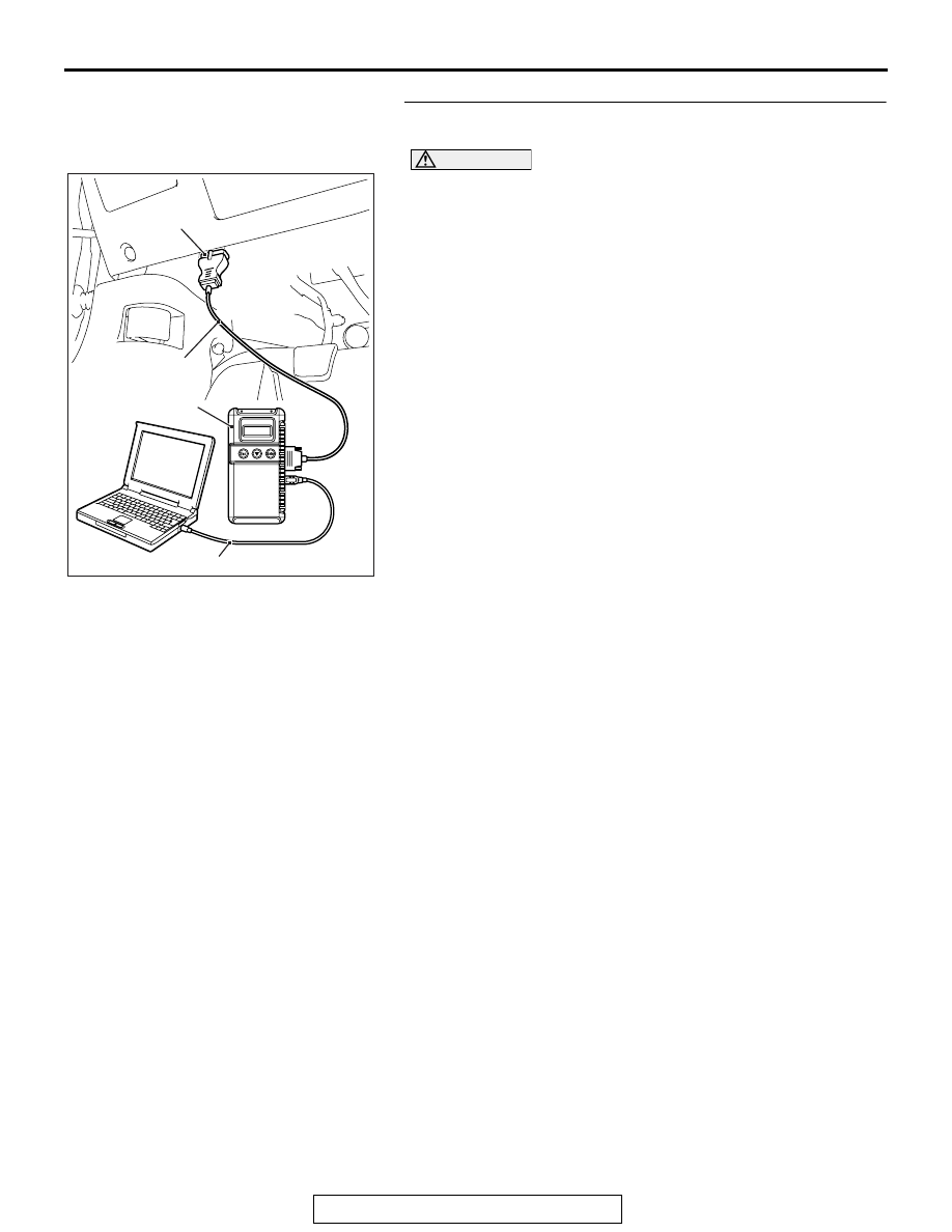
Recheck for diagnostic trouble code.
Check again if the DTC is set to the ETACS-ECU.

AC608435

Data link connector

MB991827

MB991824

MB991910

AB

CAUTION

To prevent damage to scan tool MB991958, always turn the 
ignition switch to the "LOCK" (OFF) position before con-
necting or disconnecting scan tool MB991958.
(1) Connect scan tool MB991958. Refer to "How to connect the 

Scan Tool (M.U.T.-III) 

P.54B-4

."

(2) Erase the DTC.
(3) Turn the ignition switch to the "ON" position.
(4) Check if the DTC is set.
(5) Turn the ignition switch to the "LOCK" (OFF) position.
Q: Is the DTC set?

YES <A DTC other than U1514 is set.> : Replace the 

appropriate ECU.

YES <The DTC U1514 is set.> : Replace the ETACS-ECU.
NO <The DTC is not set.> : The trouble can be an 

intermittent malfunction (Refer to GROUP 00, How to 
Cope with Intermittent Malfunction 

P.00-15

).

TROUBLESHOOTING

TSB Revision

LOCAL INTERCONNECT NETWORK (LIN)

54B-22

DTC U1515: No-Bus activity error (LIN)

LIN Communication Circuit

INTERFACE CIRCUIT

INPUT CIRCUIT

CPU

COLUMN-ECU

COLUMN
SWITCH

POWER WINDOW
MAIN SWITCH

SUNROOF MOTOR
ASSEMBLY

LIN DRIVE CIRCUIT

ETACS-ECU

JOINT
CONNECTOR (2)

LIGHTING CONTROL
SENSOR

AC708950BR

C-129 (BR)

C-102 (B)

Connectors: C-102, C-129

AC708953AG

Connector: C-212

AC708972BG

Connectors: C-301, C-316

ETACS-ECU

C-301

C-316

AC708954 AU

Connectors: D-02, D-06

D-02

D-06 (GR)

AC608167AF

Connector: E-15

TROUBLESHOOTING

TSB Revision

LOCAL INTERCONNECT NETWORK (LIN)

54B-23

.

TROUBLE JUDGMENT

The ETACS-ECU will set DTC U1515 when no com-
munication has been carried out for more than a cer-
tain period after the slave task received last valid 
data.

.

TROUBLESHOOTING HINTS

• The ETACS-ECU may be defective.

• The slave ECU may be defective.

• LIN bus lines shorted to power supply

• LIN bus lines shorted to ground

DIAGNOSIS

Required Special Tools:

• MB991223: Harness Set

• MB992006: Extra Fine Probe

• MB991958: Scan Tool (M.U.T.-III Sub Assembly)

• MB991824: Vehicles Communication Interface (V.C.I.)

• MB991827: M.U.T.-III USB Cable

• MB991910: M.U.T.-III Main Harness A (Vehicles with 

CAN communication system)

STEP 1. Check the following connectors.
Check the following connectors:

• Column switch connector C-212

• ETACS-ECU connectors C-301 and C-316

• Sunroof motor assembly connector D-06 <Vehicles with 

sunroof>

• Power window main switch connector E-15

• Lighting control sensor connector D-02 <Vehicles with auto 

light function>

Q: Are all the connectors in good condition?

YES : Go to Step 2.
NO :  Repair or replace the damaged component(s). Refer 

to GROUP 00E, Harness Connector Inspection 

P.00E-2

.

TROUBLESHOOTING

TSB Revision

LOCAL INTERCONNECT NETWORK (LIN)

54B-24

STEP 2. Check the following wiring harness.
Check the wiring harness between the following connectors:

• Wiring harness from ETACS-ECU connector C-301 (termi-

nal 1) to column switch connector C-212 (terminal 3)

• Wiring harness from ETACS-ECU connector C-316 (termi-

nal 1) to sunroof motor assembly connector D-06 (terminal 
7)

• Wiring harness from ETACS-ECU connector C-301 (termi-

nal 1) to power window main switch connector E-15 (termi-
nal 7)

• Wiring harness from ETACS-ECU connector C-316 (termi-

nal 1) to lighting control sensor connector D-02 (terminal 3)

NOTE: Also check joint connector C-102 and intermediate con-
nector C-129 for loose, corroded, or damaged terminals, or ter-
minals pushed back in the connector. If joint connector C-102 
or intermediate connector C-129 is damaged, repair or replace 
the connector as described in GROUP 00E, Harness Connec-
tor Inspection 

P.00E-2

.

Q: Are all the wiring harness wires in good condition?

YES : Go to Step 3.
NO :  The wiring harness may be damaged or the 

connector(s) may have loose, corroded or damaged 
terminals, or terminals pushed back in the connector. 
Repair the wiring harness as necessary.

STEP 3. Measure the voltage at the LIN bus lines.
Check the LIN bus lines for short to power supply.
(1) Disconnect all the ECU connectors which are connected to 

the LIN bus lines.

(2) Turn the ignition switch from "LOCK" (OFF) to "ON" position 

.

AC608254 CW

Harness side: C-212

(3) Measure the voltage between column switch connector 

C-212 (terminal 3) and ground.

• The voltmeter needle does not swing.

NOTE: If the LIN bus lines are short to power supply, the 
voltmeter indicates a constant value.


Content   ..  1155  1156  1157  1158   ..