Mitsubishi Evolution X. Manual - part 1116


  Index      Mitsubishi     Mitsubishi Evolution X - service repair manual 2008 year


Search            


Content   ..  1114  1115  1116  1117   ..


Mitsubishi Evolution X. Manual - part 1116


DIAGNOSIS

TSB Revision

CONTROLLER AREA NETWORK (CAN)

54C-99

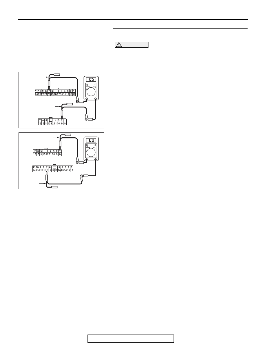
STEP 2. Check the wiring harness between joint connector 
(CAN3) C-127 and shift lever connector C-27.

CAUTION

Strictly observe the specified wiring harness repair proce-
dure. For details refer to 

P.54C-7

.

(1) Disconnect joint connector (CAN3) C-127 and shift lever 

connector C-27, and check the wiring harness.

(2) Check the wiring harness between joint connector (CAN3) 

C-127 (terminal 7) and shift lever connector C-27 (terminal 
2)

OK: Continuity exists (2 

 or less)

(3) Check the wiring harness between joint connector (CAN3) 

C-127 (terminal 20) and shift lever connector C-27 (terminal 
1)

OK: Continuity exists (2 

 or less)

Q: Is the wiring harness between joint connector (CAN3) 

C-127 and shift lever connector C-27 in good condition?
YES : 
Check the power supply circuit of the shift lever. Refer 

to GROUP 22C, Troubleshooting 

P.22C-302

 <shift 

lever>.

NO :  Repair the wiring harness between joint connector 

(CAN3) C-127 and shift lever connector C-27.

AC709707

Harness side: C-127

BL

Harness side: C-27

TEST 
HARNESS

TEST HARNESS

AC709707

Harness side: C-127

BM

Harness side: C-27

TEST HARNESS

TEST 
HARNESS

DIAGNOSIS

TSB Revision

CONTROLLER AREA NETWORK (CAN)

54C-100

DIAGNOSTIC ITEM 9: Diagnose when the scan tool cannot receive the data sent by ASC-ECU.

CAUTION

When servicing a CAN bus line, ground yourself by touching a metal object such as an unpainted 
water pipe. If you fail to do so, a component connected to the CAN bus line may be damaged.

CAN-C Communication Circuit <M/T>

ETACS-ECU

INTERFACE
CIRCUIT

CAN DRIVE
CIRCUIT

JOINT CONNECTOR
(CAN2)

JOINT CONNECTOR
(CAN3)

ASC-ECU

STEERING
WHEEL SENSOR

S-AWC-ECU

ENGINE
CONTROL
MODULE

DIAGNOSIS

TSB Revision

CONTROLLER AREA NETWORK (CAN)

54C-101

TRANSAXLE 
ASSEMBLY

ENGINE 
CONTROL 
MODULE

CAN-C Communication Circuit <TC-SST>

ETACS-ECU

INTERFACE
CIRCUIT

CAN DRIVE
CIRCUIT

JOINT CONNECTOR
(CAN2)

JOINT CONNECTOR
(CAN3)

JOINT CONNECTOR
(CAN4)

SHIFT LEVER

ASC-ECU

STEERING
WHEEL SENSOR

S-AWC-ECU

NOTE

: THE TERMINAL NUMBERS DESCRIBED 

IN THE CIRCUIT DIAGRAM AGREE WITH 
THE NUMBERS MAKED ON THE 
TRANSAXLE ASSEMBLY CONNECTOR AND 
HARNESS SIDE CONNECTOR.

DIAGNOSIS

TSB Revision

CONTROLLER AREA NETWORK (CAN)

54C-102

.

FUNCTION

If the scan tool MB991958 cannot communicate with 
the ASC-ECU, this diagnosis result will be set.

.

TROUBLE JUDGEMENT CONDITIONS

If a communication flag is not set for the ASC-ECU, 
the ETACS-ECU determines that there is a failure.

.

TROUBLESHOOTING HINTS

• Malfunction of the connector [joint connector 

(CAN3) or ASC-ECU connector improperly con-
nected]

• Malfunction of the wiring harness [open circuit 

between the ASC-ECU and the joint connector 
(CAN3), power supply circuit to the ASC-ECU]

• Malfunction of the ASC-ECU

DIAGNOSIS

Required Special Tools:

• MB991223: Harness Set

• MB992006: Extra Fine Probe

• MB991997: ASC Check Harness

STEP 1. Check joint connector (CAN3) C-127 and ASC-ECU 
connector A-05 for loose, corroded or damaged terminals, 
or terminals pushed back in the connector.

CAUTION

The strand end of the twisted wire should be within 10 cm 
(4 inches) from the connector. For details refer to 

P.54C-7

.

Q: Are joint connector (CAN3) C-127 and ASC-ECU 

connector A-05 in good condition?
YES : 
Go to Step 2.
NO :  Repair the damaged parts.

AC708948

Connector: A-05

A-05 (B)

AB

AC708951CC

Connector: C-127


Content   ..  1114  1115  1116  1117   ..