Mitsubishi Evolution X. Manual - part 1087


  Index      Mitsubishi     Mitsubishi Evolution X - service repair manual 2008 year


Search            


Content   ..  1085  1086  1087  1088   ..


Mitsubishi Evolution X. Manual - part 1087


PANIC ALARM

TSB Revision

CHASSIS ELECTRICAL

54A-709

DIAGNOSIS

STANDARD FLOW OF DIAGNOSTIC 
TROUBLESHOOTING

M1547001200184

Refer to GROUP 00 

− Contents of troubleshootin

P.00-7

.

DIAGNOSTIC FUNCTION

M1547001300051

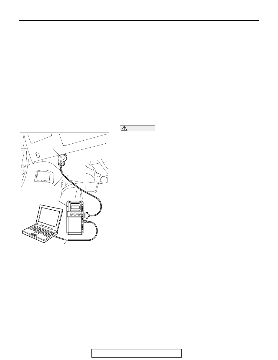
HOW TO CONNECT THE SCAN TOOL (M.U.T.-III)

Required Special Tools:

• MB991958: Scan Tool (M.U.T.-III Sub Assembly)

• MB991824: Vehicle Communication Interface (V.C.I.)

• MB991827: M.U.T.-III USB Cable

• MB991910: M.U.T.-III Main Harness A (Vehicles with 

CAN communication system)

CAUTION

To prevent damage to scan tool MB991958, always turn the 
ignition switch to the "LOCK" (OFF) position before con-
necting or disconnecting scan tool MB991958.
1. Ensure that the ignition switch is at the "LOCK" (OFF) 

position.

2. Start up the personal computer.
3. Connect special tool MB991827 to special tool MB991824 

and the personal computer.

4. Connect special tool MB991910 to special tool MB991824.
5. Connect special tool MB991910 to the data link connector.
6. Turn the power switch of special tool MB991824 to the "ON" 

position.
NOTE: When special tool MB991824 is energized, special 
tool MB991824 indicator light will be illuminated in a green 
color.

7. Start the scan tool system on the personal computer.
NOTE: Disconnecting scan tool MB991958 is the reverse of the 
connecting sequence, making sure that the ignition switch is at 
the "LOCK" (OFF) position.

HOW TO READ AND ERASE DIAGNOSTIC 
TROUBLE CODES

Required Special Tools:

• MB991958: Scan Tool (M.U.T.-III Sub Assembly)

• MB991824: Vehicle Communication Interface (V.C.I.)

• MB991827: M.U.T.-III USB Cable

• MB991910: M.U.T.-III Main Harness A (Vehicles with 

CAN communication system)

AC608435

Data link connector

MB991827

MB991824

MB991910

AB

PANIC ALARM

TSB Revision

CHASSIS ELECTRICAL

54A-710

CAUTION

To prevent damage to scan tool MB991958, always turn the 
ignition switch to the "LOCK" (OFF) position before con-
necting or disconnecting scan tool MB991958.
NOTE: If the battery voltage is low, diagnostic trouble codes will 
not be set. Check the battery if scan tool MB991958 does not 
display.
1. Connect scan tool MB991958 to the data link connector.
2. Turn the ignition switch to the "ON" position.
3. Select "System select" from the start-up screen.
4. Select "From 2006 MY" of "Model Year." When the "Vehicle 

Information" is displayed, check the contents.

5. Select "ETACS" from "System List", and press the "OK" 

button.
NOTE: When the "Loading Option Setup" list is displayed, 
check the applicable item.

6. Select "Diagnostic Trouble Code."
7. If a DTC is set, it is shown.
8. Choose "Erase DTCs" to erase the DTC.

TROUBLE SYMPTOM CHART

M1547001500282

SYMPTOM PROCEDURES

Panic alarm does not work normally.

.

TECHNICAL DESCRIPTION (COMMENT)

If keyless operation system <KOS> or keyless entry 
system <WCM> is normal, the ETACS-ECU may be 
defective.

.

TROUBLESHOOTING HINTS

• Keyless operation system <KOS> or keyless 

entry system <WCM> may be defective

• The ETACS-ECU may be defective

• Function is not set with the customization.

DIAGNOSIS

Required Special Tools:

• MB991958 Scan Tool (M.U.T.-III Sub Assembly)

• MB991824: Vehicle Communication Interface (V.C.I.)

• MB991827 M.U.T.-III USB Cable

• MB991910 M.U.T.-III Main Harness A (Vehicles with 

CAN communication system)

Trouble symptom

Reference 
page

Panic alarm does not work normally.

P.54A-688

PANIC ALARM

TSB Revision

CHASSIS ELECTRICAL

54A-711

STEP 1. Check if the theft-alarm is normally set and the 
exterior protection can be executed.
Check that the theft-alarm works normally.
Q: Does the theft-alarm work normally?

YES : Go to Step 2.
NO :  Troubleshoot the theft-alarm (Refer to 

P.54A-687

).

 STEP 2. Using scan tool MB991958, read the diagnostic 
trouble code. 
Check if DTC is set to the KOS-ECU <Vehicles with KOS> or 
WCM <Vehicles with WCM>.

CAUTION

To prevent damage to scan tool MB991958, always turn the 
ignition switch to the "LOCK" (OFF) position before con-
necting or disconnecting scan tool MB991958.
(1) Connect scan tool MB991958. Refer to "How to connect the 

scan tool (M.U.T.-III) 

P.54A-709

."

(2) Turn the ignition switch to the "ON" position.
(3) Check whether the KOS or WCM related DTC is set.
(4) Turn the ignition switch to the "LOCK" (OFF) position.
Q: Is the DTC set?

YES <vehicles with KOS> : Troubleshoot the KOS (Refer 

to GROUP 42B, KOS 

P.42B-20

).

YES <vehicles with WCM> : Troubleshoot the WCM (Refer 

to GROUP 42C, WCM 

P.42C-14

).

NO  :  Go to Step 3.

STEP 3. Check keyless operation system <KOS> or 
keyless entry system <WCM>.
Q: Do keyless operation system <KOS> or keyless entry 

system <WCM> work normally?
YES : 
Go to Step 4.
NO <vehicles with KOS> : Troubleshoot the KOS (Refer to 

GROUP 42B, KOS 

P.42B-172

).

NO <vehicles with WCM> : Troubleshoot the WCM (Refer 

to GROUP 42C, WCM 

P.42C-84

).

AC608435

Data link connector

MB991827

MB991824

MB991910

AB

PANIC ALARM

TSB Revision

CHASSIS ELECTRICAL

54A-712

STEP 4. Using scan tool MB991958, check the 
configuration function. 
(1) Turn the ignition switch to the "ON" position.
(2) Use the ETACS-ECU customization function to check that 

the "Panic alarm switch" is set to "Enable".

(3) Turn the ignition switch to the "LOCK" (OFF) position.
Q: Is the "Panic alarm switch" set to "Enable"?

YES  : Replace the ETACS-ECU.
NO :  Use the ETACS-ECU customization function to set 

the "Panic alarm switch" to "Enable"(Refer to 

P.54A-712

).

REMOVAL AND INSTALLATION

M1547002600044

Panic alarm system component parts

• Headlight assembly (Refer to 

P.54A-184

).

• Horn (Refer to 

P.54A-268

).

• Key reminder switch (Refer to 

P.52A-7

).

ON-VEHICLE SERVICE

CUSTOMIZATION FUNCTION

M1547003400214

By operating the ETACS system or MMCS of scan 
tool MB991958, the following functions can be pro-
grammed. The programmed information is held even 
when the battery is disconnected.

Adjustment item 
(scan tool 
display)

Adjustment item

Adjustment contents (scan tool 
display)

Adjusting contents

Panic alarm switch With/without panic 

alarm function

Disable

Without function

Enable

With function (default)


Content   ..  1085  1086  1087  1088   ..