Content .. 1082 1083 1084 1085 ..
Mitsubishi Evolution X. Manual - part 1084
THEFT ALARM
TSB Revision
CHASSIS ELECTRICAL
54A-697
.
TECHNICAL DESCRIPTION (COMMENT)
If theft-horn does not sound, the theft-horn input sig-
nal circuit or the ETACS-ECU may be defective.
Also, the theft-alarm function and horn may have
been disabled with a configuration function.
.
TROUBLESHOOTING HINTS
• Theft-alarm horn may be defective
• Theft-alarm horn relay may be defective
• The ETACS-ECU may be defective
• The wiring harness or connectors may have
loose, corroded, or damaged terminals, or termi-
nals pushed back in the connector
DIAGNOSIS
Required Special Tools:
• MB992006: Extra fine probe
• MB991223: Harness set
• MB991958: Scan Tool (M.U.T.-III Sub Assembly)
• MB991824: Vehicle Communication Interface (V.C.I.)
• MB991827: M.U.T.-III USB Cable
• MB991910: M.U.T.-III Main Harness A (Vehicles with
CAN communication system)
AC708948AJ
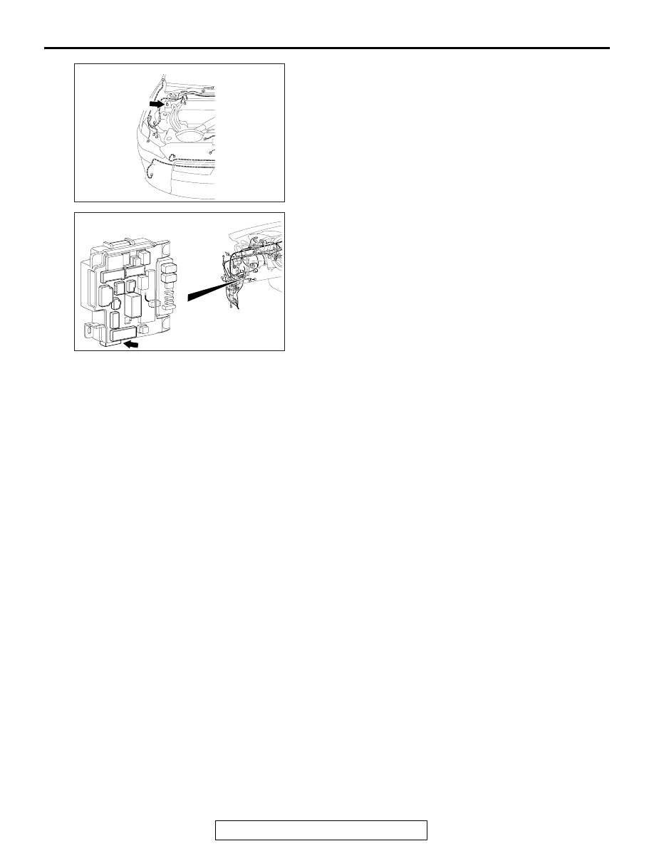
Connector: A-59
A-59 (B)
AC708972AP
Connector: C-312
ETACS-ECU