Mitsubishi Evolution X. Manual - part 1067


  Index      Mitsubishi     Mitsubishi Evolution X - service repair manual 2008 year


Search            


Content   ..  1065  1066  1067  1068   ..


Mitsubishi Evolution X. Manual - part 1067


ETACS

TSB Revision

CHASSIS ELECTRICAL

54A-629

STEP 2. Battery check
Refer to 

P.54A-9

.

Q: Is the battery in good condition?

YES : Go to Step 3.
NO :  Charge or replace the battery.

STEP 3. Charging system check
Refer to GROUP 16 

− Output Current Test 

P.16-8

.

Q: Is the charging system in good condition?

YES : Go to Step 4.
NO :  Repair or replace the charging system component(s).

STEP 4. Check ETACS-ECU connector C-317 for loose, 
corroded or damaged terminals, or terminals pushed back 
in the connector.
Q: Is ETACS-ECU connector C-317 in good condition?

YES : Go to Step 5.
NO :  Repair or replace the component(s). Refer to GROUP 

00E, Harness Connector Inspection 

P.00E-2

.

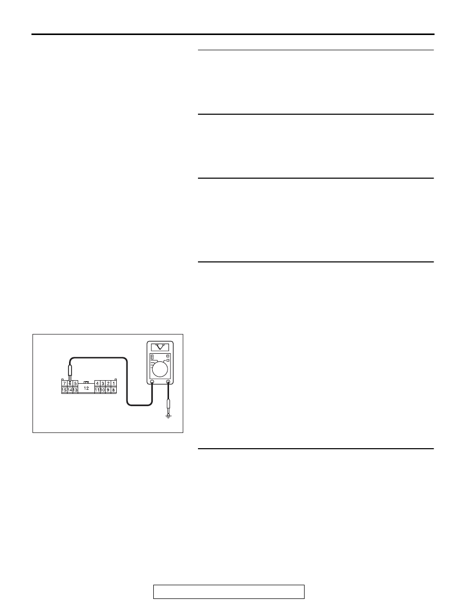
STEP 5. Check the ignition switch (IG1) circuit to the 
ETACS-ECU. Measure the voltage at ETACS-ECU 
connector C-317.
(1) Disconnect ETACS-ECU connector C-317 and measure the 

voltage available at the wiring harness side of the 
connector.

(2) Turn the ignition switch to the "ON" position.
(3) Measure the voltage between terminal 6 and ground.

• The voltage should measure approximately 12 volts 

(battery positive voltage).

Q: Is the measured voltage approximately 12 volts (battery 

positive voltage)?
YES : 
Go to Step 7.
NO :  Go to Step 6.

STEP 6. Check the wiring harness between ETACS-ECU 
connector C-317 (terminal 6) and the ignition switch (IG1).
Check the power supply line for open circuit and short circuit.
Q: Is the wiring harness between ETACS-ECU connector 

C-317 (terminal 6) and the ignition switch (IG1) in good 
condition?
YES : 
No action is necessary and testing is complete.
NO :  The wiring harness may be damaged or the 

connector(s) may have loose, corroded or damaged 
terminals, or terminals pushed back in the connector. 
Repair the wiring harness as necessary.

AC608254 BG

Harness side: C-317

ETACS

TSB Revision

CHASSIS ELECTRICAL

54A-630

STEP 7. Recheck for diagnostic trouble .
Check again if the DTC is set to the ETACS-ECU.
(1) Erase the DTC.
(2) Turn the ignition switch from "LOCK" (OFF) position to "ON" 

position.

(3) Check if DTC is set.
(4) Turn the ignition switch to the "LOCK" (OFF) position.
Q: Is the DTC set?

YES : Replace the ETACS-ECU.
NO :  The trouble can be an intermittent malfunction (Refer 

to GROUP 00, How to Cope with Intermittent 
Malfunction 

P.00-15

).

SERVICE DATA

M1545001300293

NOTE: For some information result read out by the 
ECU, the specific items may not be displayed.

Item No. Display on M.U.T.-III

Check conditions

Normal conditions

1

CAN-H voltage (CAN-C)

2.0

−4.5 V

2

CAN-L voltage (CAN-C)

0.5

−3.0 V

200

Original VIN writing status

When writing status is normal

Comp/Unperformed 
or Comp and locked

When writing status is abnormal ECU internal Err

201

Current VIN writing status

When writing status is normal

Comp/Unperformed

When writing status is abnormal ECU internal Err

202

Internal error

When no error is present

No error

When an error is present

EEPROM error or 
Boot loader Err or 
EEPROM/Boot or 
ADC Error or 
ADC/EEPROM error 
or ADC/Boot error or 
ADC/Boot/EEPROM 
or PLL Error or 
PLL/EEPROM error 
or PLL/EEPROM 
error or 
PLL/Boot/EEPROM 
or PLL/ADC error or 
PLL/ADC/EEPROM 
or PLL/ADC/Boot or 
PLL/ADC/Boot/ROM

203

Process error

When no error is present

No error

When an error is present

Interrupt error or 
Switch error or 
Sequence error or 
Stck pointer Err or 
Dispatch call Er or 
Other error

204

Coding counter

0

−255 times

ETACS

TSB Revision

CHASSIS ELECTRICAL

54A-631

205

Coding counter Option 

0

−255 times

206

Headlight LO ON duty

When low-beam headlights are 
on

100 %

When low-beam headlights are 
off

0 %

207

Fan control relay ON duty

When the fan is in operation

100 %

When the fan is stopped

0 %

208

Dome light ON duty

When the room light is turned 
from ON to OFF

When the light is 
dimmed from 100% 
(when ON) to 0%

209

Gate light ON duty

When the trunk is opened

100 %

When the trunk is closed

0 %

210

IG key illumination

When the door is opened

100 %

When the door is closed

0 %

211

Headlight Hi

When high-beam headlights are 
on

ON

When high-beam headlights are 
off

OFF

212

Front fog light

When fog lights are on

ON

When fog lights are off

OFF

213

Horn theft horn

When the security alarm is 
active

ON

When the security alarm is not 
active

OFF

215

Security indicator

When the security alarm is 
active

ON

When the security alarm is not 
active

OFF

216

IG1-2 fuel pump

Ignition switch: ON position

ON

Ignition switch: Other than ON

OFF

218

Taillight

When taillights and position 
lights are on

ON

When taillights and position 
lights are off

OFF

219

Turn RH/LH light

When turn-signal lights are on

ON

When turn-signal lights are off

OFF

220

Blower fan

Ignition switch: ON position

ON

Ignition switch: Other than ON

OFF

221

Defogger

1. Engine: ON
2. Defogger switch: ON

ON

Other than above

OFF

Item No. Display on M.U.T.-III

Check conditions

Normal conditions

ETACS

TSB Revision

CHASSIS ELECTRICAL

54A-632

222

Interior light cut

When the interior light is ON

ON

When the light is turned off by 
the activation of interior light 
automatic cut function

OFF

224

Door lock

When locking is performed by 
the central door lock

ON

Other than above

OFF

227

Door unlock

When unlocking is performed by 
the central door lock

ON

Other than above

OFF

228

Dr door unlock

When unlocking is performed by 
the central door lock

ON

Other than above

OFF

230

Trunk/gate opener

Trunk open switch: ON

ON

Other than above

OFF

232

ACC Relay

Ignition switch: ACC or ON

ON

Ignition switch: Other than ACC 
or ON

OFF

233

Fan Lo

When the fan is in Lo operation ON
When the fan is stopped

OFF

234

Fan Hi

When the fan is in Hi operation ON
When the fan is stopped

OFF

235

Front wiper ACT

When the windshield wiper is in 
operation

ON

Other than above

OFF

236

Front wiper Lo/Hi

When the windshield wiper is in 
high-speed operation

ON

Other than above

OFF

237

Front washer

The windshield washer is in 
operation

ON

Other than above

OFF

240

Power window

Ignition switch: ON position

ON

Ignition switch: 30 seconds after 
turned to the OFF position

ON 

→ OFF

252

Ambient temperature sensor

Ignition switch: ON position

0

−5 V

253

Voltage sensing of IOD Line

Always

Battery positive 
voltage

254

IG voltage

Ignition switch: ON position

Battery positive 
voltage

256

Dr door ajar switch

Driver's door: Open

Open

Driver's door: Closed

Close

257

As door ajar switch

Front passenger's door: Open

Open

Front passenger's door: Closed Close

Item No. Display on M.U.T.-III

Check conditions

Normal conditions


Content   ..  1065  1066  1067  1068   ..