Mitsubishi Evolution X. Manual - part 1021


  Index      Mitsubishi     Mitsubishi Evolution X - service repair manual 2008 year


Search            


Content   ..  1019  1020  1021  1022   ..


Mitsubishi Evolution X. Manual - part 1021


MMCS

TSB Revision

CHASSIS ELECTRICAL

54A-445

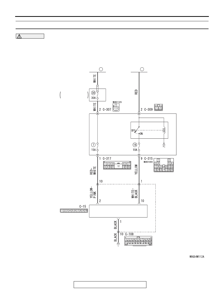
Inspection Procedure 12: Check the CAN box unit power supply circuit.

CAUTION

Before replacing the ECU, ensure that the power supply circuit, the ground circuit and the communi-
cation circuit are normal. (Check that the voltage is 10 V or more.)

CAN Box Unit Power Supply Circuit

ACC
RELAY 2

ETACS-
ECU

FUSIBLE
LINK

36

FUSIBLE
LINK

37

CAN BOX UNIT

RELAY BOX
 ENGINE 
 COMPARTMENT

MMCS

TSB Revision

CHASSIS ELECTRICAL

54A-446

.

TECHNICAL DESCRIPTION (COMMENT)

If the CAN box unit functions do not work at all, the 
CAN box unit power supply system, ground system, 
or CAN box unit may have a problem.

.

PROBABLE CAUSES

• The wiring harness or connectors may have 

loose, corroded, or damaged terminals, or termi-
nals pushed back in the connector

• The CAN box unit may be defective

DIAGNOSIS

Required Special Tools:

• MB991223: Harness Set

• MB992006: Extra Fine Probe

• MB991958 Scan Tool (M.U.T.-III Sub Assembly)

• MB991824: Vehicle Communication Interface (V.C.I.)

• MB991827 M.U.T.-III USB Cable

• MB991910 M.U.T.-III Main Harness A

STEP 1. Check CAN box unit connectors C-15 for loose, 
corroded or damaged terminals, or terminals pushed back 
in the connector.
Q: Is CAN box unit connectors C-15 in good condition?

YES : Go to Step 2.
NO :  Repair or replace the damaged component(s). Refer 

to GROUP 00E, Harness Connector Inspection 

P.00E-2

.

AC708951BP

Connectors: C-15, C-108

C-15

C-108

AC708950

Connector: C-105

BL

AC708972BC

Connectors: C-307, C-315, C-317

ETACS-ECU

C-307 (B)

C-315

C-317

MMCS

TSB Revision

CHASSIS ELECTRICAL

54A-447

STEP 2. Check the ground circuit to the CAN box unit. 
Measure the resistance at CAN box unit connector C-15.
(1) Disconnect CAN box unit connector C-15 and measure the 

resistance available at the wiring harness side of the 
connector.

(2) Measure the resistance value between CAN box unit 

connector C-15 terminal 1 and ground.

OK: The resistance should be 2 ohms or less.

Q: Is the measured resistance 2 ohms or less?

YES : Go to Step 4.
NO :  Go to Step 3.

STEP 3. Check the wiring harness between CAN box unit 
connector C-15 (terminal 1) and the ground.

• Check the ground wires for open circuit.

NOTE: Also check intermediate connector C-108 for loose, cor-
roded, or damaged terminals, or terminals pushed back in the 
connector. If intermediate connector C-108 is damaged, repair 
or replace the connector as described in GROUP 00E, Harness 
Connector Inspection 

P.00E-2

.

Q: Is the wiring harness between CAN box unit connector 

C-15 (terminal 1) and the ground in good condition?
YES : 
Go to Step 4.
NO :  The wiring harness may be damaged or the 

connector(s) may have loose, corroded or damaged 
terminals, or terminals pushed back in the connector. 
Repair the wiring harness as necessary.

STEP 4. Check the battery power supply circuit to the CAN 
box unit. Measure the voltage at CAN box unit connectors 
C-15.
(1) Disconnect CAN box unit connectors C-15 measure the 

voltage available at the wiring harness side of the 
connector.

(2) Measure the voltage between CAN box unit connector C-15 

terminal 2 and ground.

OK:Battery voltage.

Q: Is the measured voltage battery voltage?

YES : Go to Step 6.
NO :  Go to Step 5.

AC709322 BH

Harness side: C-15

AC709325 AN

Harness side: C-15

MMCS

TSB Revision

CHASSIS ELECTRICAL

54A-448

STEP 5. Check the wiring harness between CAN box unit 
connector C-15 (terminal 2) and fusible link (36).

• Check the power supply line for open circuit and short cir-

cuit.

NOTE: Also check intermediate connector C-105 and 
ETACS-ECU connectors C-307 and C-317 for loose, corroded, 
or damaged terminals, or terminals pushed back in the connec-
tor. If intermediate connector C-108 or ETACS-ECU connector 
C-307 or C-317 is damaged, repair or replace the connector as 
described in GROUP 00E, Harness Connector Inspection 

P.00E-2

.

Q: Is the wiring harness between CAN box unit connector 

C-15 (terminal 2) and fusible link (36) in good condition?
YES : 
Go to Step 6.
NO :  The wiring harness may be damaged or the 

connector(s) may have loose, corroded or damaged 
terminals, or terminals pushed back in the connector. 
Repair the wiring harness as necessary. The system 
should communicate with the CAN box unit normally.

STEP 6. Using scan tool MB991958, check data list.
Check the input signal of ACC relay.

• Turn the ignition switch to the ACC position.

OK: Normal condition is displayed.

Q: Is the check result normal?

YES : Go to Step 7.
NO :  Refer to GROUP 54A, ETACS, Diagnosis 

− Inspection 

Procedure 1 "The ignition switch (ACC) signal is not 
received 

P.54A-640

."

STEP 7. Check ETACS-ECU connector C-315 for loose, 
corroded or damaged terminals, or terminals pushed back 
in the connector.
Q: Is ETACS-ECU connector C-315 in good condition?

YES : Go to Step 8.
NO :  Repair or replace the damaged component(s). Refer 

to GROUP 00E, Harness Connector Inspection 

P.00E-2

.

Item No.

Item name

Normal 
conditions

Item 288

ACC switch

ON


Content   ..  1019  1020  1021  1022   ..