Mitsubishi Evolution X. Manual - part 1015


  Index      Mitsubishi     Mitsubishi Evolution X - service repair manual 2008 year


Search            


Content   ..  1013  1014  1015  1016   ..


Mitsubishi Evolution X. Manual - part 1015


MMCS

TSB Revision

CHASSIS ELECTRICAL

54A-421

STEP 12. Check the wiring harness between audio 
amplifier connector D-25 (terminal 25, 35, 36) and fusible 
link (36).
NOTE: Also check intermediate connector C-47 for loose, cor-
roded, or damaged terminals, or terminals pushed back in the 
connector. If intermediate connector C-47 is damaged, repair or 
replace the connector as described in GROUP 00E, Harness 
Connector Inspection 

P.00E-2

.

• Check the power supply line for open circuit and short cir-

cuit.

Q: Is the wiring harness between audio amplifier connector 

D-29 (terminal 25, 35, 36) and fusible link (36) in good 
condition?
YES : 
Go to Step 13.
NO :  The wiring harness may be damaged or the 

connector(s) may have loose, corroded or damaged 
terminals, or terminals pushed back in the connector. 
Repair the wiring harness as necessary. 

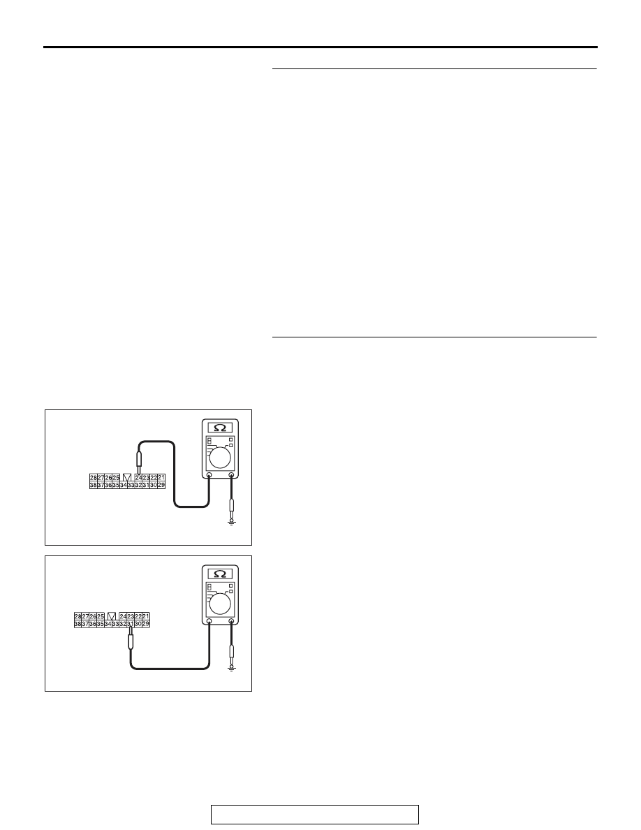
STEP 13. Check the ground circuit to the audio amplifier. 
Measure the resistance at audio amplifier connector D-29.
(1) Disconnect audio amplifier connector D-29, and measure 

the resistance available at the wiring harness side of the 
connector.

(2) Measure the resistance between terminal 24 and ground.

OK: The resistance should be 2 ohms or less

(3) Measure the resistance between terminal 31 and ground.

OK: The resistance should be 2 ohms or less

AC709322 AT

Harness side: D-29

AC709322 AU

Harness side: D-29

MMCS

TSB Revision

CHASSIS ELECTRICAL

54A-422

(4) Measure the resistance between terminal 32 and ground.

OK: The resistance should be 2 ohms or less

Q: Is the measured resistance 2 ohms or less?

YES : Go to Step 15.
NO :  Go to Step 14.

STEP 14. Check the wiring harness between audio 
amplifier connector D-29 (terminal 24, 31, 32) and ground.

• Check the ground wires for open circuit.

Q: Is the wiring harness between audio amplifier connector 

D-25 (terminal 24, 31, 32) and ground in good condition?
YES : 
The trouble can be an intermittent malfunction (Refer 

to GROUP 00, How to use 
Troubleshooting/inspection Service Points, How to 
Cope with Intermittent Malfunction 

P.00-15

).

NO :  The wiring harness may be damaged or the 

connector(s) may have loose, corroded or damaged 
terminals, or terminals pushed back in the connector. 
Repair the wiring harness as necessary. 

STEP 15. Check multivision display connector C-09, C-13 
and audio amplifier connector D-30 for loose, corroded or 
damaged terminals, or terminals pushed back in the 
connector.
Q: Is multivision display connector C-09, C-13 and audio 

amplifier connector D-30 in good condition?
YES : 
Go to Step 16.
NO :  Repair or replace the damaged component (Refer to 

GROUP 00E, Harness Connector Inspection 

P.00E-2

).

STEP 16. Check the wiring harness between multivision 
display connector C-09 (terminal 72) and audio amplifier 
connector D-30 (terminal 3)
NOTE: Also check intermediate connectors C-110 and C-24 for 
loose, corroded, or damaged terminals, or terminals pushed 
back in the connector. If intermediate connector C-110 or C-24 
is damaged, repair or replace the connector as described in 
GROUP 00E, Harness Connector Inspection 

P.00E-2

.

• Check the communication lines for open circuit and short 

circuit.

AC709322 AV

Harness side: D-29

MMCS

TSB Revision

CHASSIS ELECTRICAL

54A-423

Q: Is the wiring harness between multivision display 

connector C-09 (terminal 72) and audio amplifier 
connector D-30 (terminal 3) in good condition?
YES : 
Go to Step 17.
NO :  The wiring harness may be damaged or the 

connector(s) may have loose, corroded or damaged 
terminals, or terminals pushed back in the connector. 
Repair the wiring harness as necessary. 

STEP 17. Check the wiring harness between multivision 
display connector C-13 (terminal 6) and audio amplifier 
connector D-29 (terminal 34)
NOTE: Also check intermediate connectors C-110 and C-24 for 
loose, corroded, or damaged terminals, or terminals pushed 
back in the connector. If intermediate connector C-110 or C-24 
is damaged, repair or replace the connector as described in 
GROUP 00E, Harness Connector Inspection 

P.00E-2

.

• Check the communication lines for open circuit and short 

circuit.

Q: Is the wiring harness between multivision display 

connector C-13 (terminal 6) and audio amplifier 
connector D-29 (terminal 34) in good condition?
YES : 
Go to Step 18.
NO :  The wiring harness may be damaged or the 

connector(s) may have loose, corroded or damaged 
terminals, or terminals pushed back in the connector. 
Repair the wiring harness as necessary. 

STEP 18. Retest the system
Check that the audio sound is output.
Q: Is the check result normal?

YES : The trouble can be an intermittent malfunction (Refer 

to GROUP 00 

− How to use 

Troubleshooting/inspection Service Points 

− How to 

Cope with Intermittent Malfunction 

P.00-15

).

NO :  Go to Step 19.

STEP 19. Retest the system
Temporarily replace the multivision display, and check if the 
sound is output.
Q: Is the check result normal?

YES : Replace the multivision display.
NO :  Replace the audio amplifier.

MMCS

TSB Revision

CHASSIS ELECTRICAL

54A-424

Inspection Procedure 3: No sound is heard from one of the speakers. <Vehicles with audio amplifier>

CAUTION

Before replacing the ECU, ensure that the power supply circuit, the ground circuit, and the communi-
cation circuit are normal. (Check that the voltage is 10 V or more.)

Speaker System Circuit

AUDIO AMPLIFIER

TWEETER
(LH)

TWEETER
(RH)

FRONT DOOR 
SPEAKER (LH)

FRONT DOOR 
SPEAKER (RH)

REAR DOOR
SPEAKER
(LH)

REAR DOOR
SPEAKER
(RH)

SUB WOOFER


Content   ..  1013  1014  1015  1016   ..