Mitsubishi Evolution X. Manual - part 101


  Index      Mitsubishi     Mitsubishi Evolution X - service repair manual 2008 year


Search            


Content   ..  99  100  101  102   ..


Mitsubishi Evolution X. Manual - part 101


LIGHTING

TSB Revision

CHASSIS ELECTRICAL

54A-7

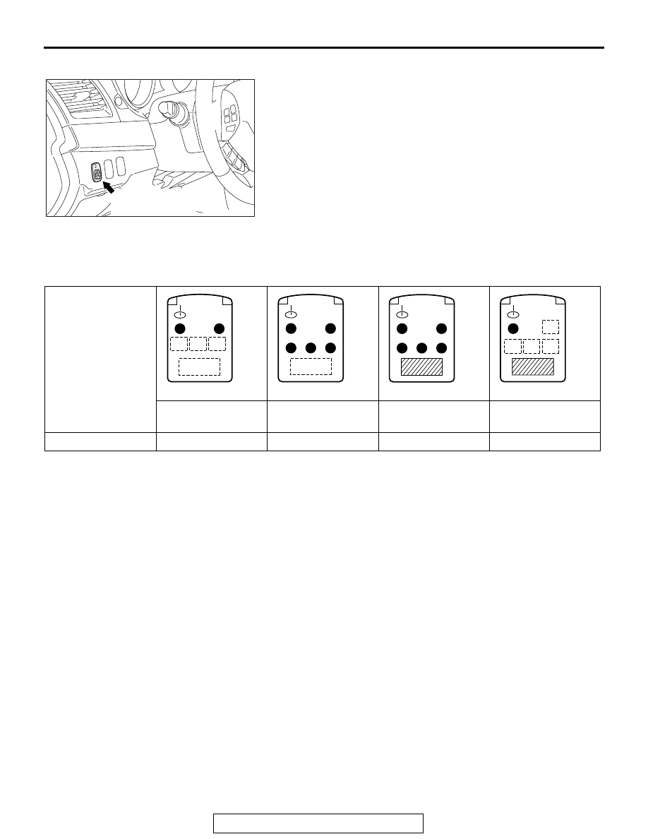
HEADLIGHT MANUAL LEVELING SYSTEM

The beam direction of the headlights changes according to the 
number of passengers and the amount of load. The headlight 
manual leveling function is a system that allows the driver to 
change the direction of headlight beam so that the drivers of 
oncoming cars are not dazzled by the headlights. The headlight 
leveling switch allows changing the direction in five steps: 0 to 
4.
NOTE: As the position value of headlight leveling switch 
increases, the direction of the headlight becomes lower.

.

RELATIONSHIP BETWEEN THE SWITCH POSITIONS AND THE NUMBER OF 
PASSENGERS/LOADS

NOTE: 

.

Each switch position is for reference. In each switch position, when the headlight direction is still too high, 
turn the switch to a position that is one-level higher.

Before the adjustment of beam height, set the switch to the 0 position (beam direction is at the uppermost 
position).

After unloading passengers or luggage, always return the switch to the 0 position.

.

AC608421 AB

Headlight leveling 
switch

Passenger and load

One or two 
passengers

Five passengers

Five passengers 
and heavy loads

Driver and heavy 
loads

Switch position

0

1

2

2

AC508573

AC508574

AC508591

AC508592

LIGHTING

TSB Revision

CHASSIS ELECTRICAL

54A-8

OPERATION

1. The headlight leveling switch increases the 

resistance as it is turned from 0 to 4. Turning the 
headlight leveling switch changes the voltage at 
point A. When the headlight leveling switch is 
turned from 0 to 4, the voltage at point A 
decreases. Upon detection of this voltage change, 
the headlight leveling unit turns the motor to lower 
the beam direction. At this time, the resistance of 
the variable resistor in the headlight assembly 
changes, and the voltage at point B decreases 
gradually. When the voltages at points A and B 
become equal, the headlight leveling unit stops 
the motor.

2. Turning the headlight leveling switch from 4 to 0 

increases the voltage at point A, and then the 
headlight leveling unit turns the motor in the 
direction opposite to that mentioned in Item 1, 
increasing the voltage at point B. When the 
voltages at points A and B become equal, the 
headlight leveling unit stops the motor.

3. The headlight leveling unit detects voltage 

changes caused by headlight leveling switch 
operation, and turns the motor to change the 
directions of the headlight reflectors for the 
adjustment of the headlight beam direction.

AC302836

AC314086AB

Variable resistor

Headlight 
leveling 
unit (LH)

Headlight 
leveling 
unit (RH)

CPU

0

1

2 3

4

ILL

A

B

A

B

CPU

Fuse

Headlight
leveling
switch

Variable resistor

Motor
drive
circuit

Voltage
comparison
circuit

Motor
drive
circuit

Voltage
comparison
circuit

LIGHTING

TSB Revision

CHASSIS ELECTRICAL

54A-9

INTERIOR LIGHT

M2544300400351

.

CONSTRUCTION DIAGRAM

AC709153

AB

Rear dome light

Front dome light
(Front dome light / reading lights)

Luggage compartment light

AC709131

AB

Ignition key cylinder
illumination light

Center console
down light

LIGHTING

TSB Revision

CHASSIS ELECTRICAL

54A-10

• A front dome light, installed to the front part of the 

roof, has been equipped with the lens-push type 
front dome light / reading light which can be oper-
ated easily from the driver's and front passen-
ger's seat, offering excellent operability for 
turning on and off the light.

• The rear dome light, which illuminates the rear 

passenger's seat, is installed above the rear seat. 
<Vehicle without sunroof>

• The luggage compartment light is installed to the 

upper part of the luggage compartment.

• An ignition key cylinder light has been added to 

the ignition key cylinder. <Vehicle without KOS>

• The center console down light has been installed 

to the upper surface of the center lower box.

• The dimmer interior light control function and igni-

tion key cylinder illumination light control function 
have been adopted for the interior light (Refer to 
Function and Control by ETACS-ECU 

P.54A-10

 ).

.

SPECIFICATIONS

FUNCTION AND CONTROL BY ETACS-ECU.

M2544300600377

Following functions are controlled by ETACS-ECU.

Item

Specification

Front dome light (front dome light / reading light) W 

× quantity

× 2

Rear dome light W

8

Luggage compartment light W

5

Ignition key cylinder illumination light W

1.5

Center console down light

LED type

Function

Function 
description

Headlight

Headlight automatic-shutdown function

P.54A-11

Auto light function <Vehicles with lighting control sensor>

P.54A-11

Flasher timer function

Turn-signal light

P.54A-12

Comfort flasher function

P.54A-12

Hazard warning light

P.54A-12

Daytime running light

Daytime running light function

P.54A-13

Fog light

Front fog light function

P.54A-14

Interior light

Interior light dimmer control function

P.54A-15

Interior light automatic-shutoff function

P.54A-15

Ignition key cylinder illumination light control function

P.54A-16


Content   ..  99  100  101  102   ..