Content .. 1006 1007 1008 1009 ..
Mitsubishi Evolution X. Manual - part 1008
MMCS
TSB Revision
CHASSIS ELECTRICAL
54A-393
TROUBLESHOOTING HINTS
• The CAN bus line may be defective
• The CAN box unit may be defective
• The ETACS-ECU may be defective
DIAGNOSIS
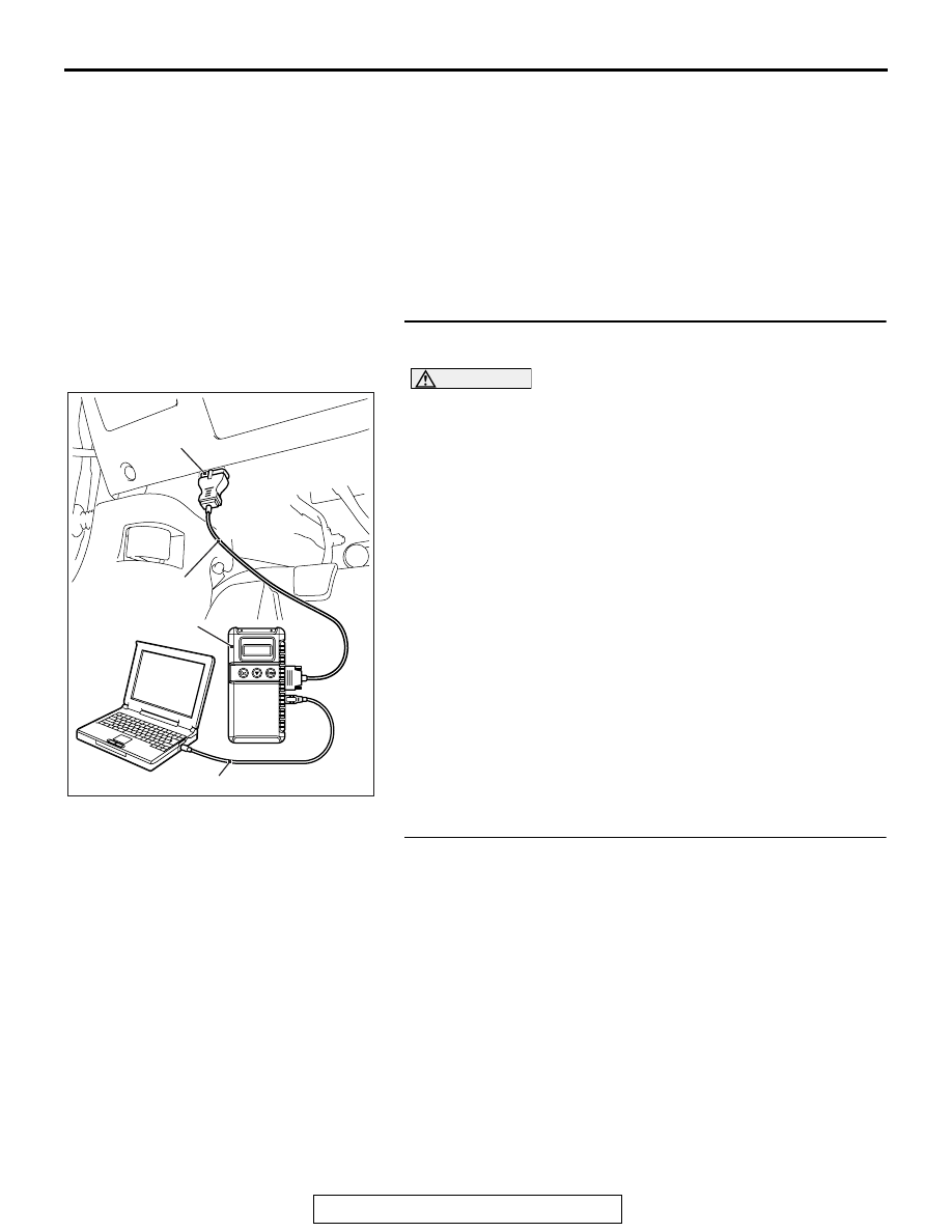
Required Special Tools:
• MB991958 Scan Tool (M.U.T.-III Sub Assembly)
• MB991824: Vehicles Communication Interface (V.C.I.)
• MB991827 M.U.T.-III USB Cable
• MB991910 M.U.T.-III Main Harness A (Vehicles with
CAN communication system)
STEP 1. Using scan tool MB991958, diagnose the CAN bus
line.
CAUTION
To prevent damage to scan tool MB991958, always turn the
ignition switch to the "LOCK" (OFF) position before con-
necting or disconnecting scan tool MB991958.
(1) Connect scan tool MB991958. Refer to "How to connect the
Scan Tool (M.U.T.-III)
."
(2) Turn the ignition switch to the "ON" position.
(3) Diagnose the CAN bus line.
(4) Turn the ignition switch to the "LOCK" (OFF) position.
Q: Is the CAN bus line found to be normal?
YES : Go to Step 2.
NO : Repair the CAN bus line (Refer to GROUP 54C,
).
STEP 2. Using scan tool MB991958, read the ETACS-ECU
diagnostic trouble code.
Check again if the DTC is set to the ETACS-ECU.
Q: Is the DTC set?
YES : Diagnose the ETACS-ECU (Refer to
).
NO : Go to Step 3.
AC608435
Data link connector
MB991827
MB991824
MB991910
AB