Mitsubishi Evolution X. Manual - part 66


  Index      Mitsubishi     Mitsubishi Evolution X - service repair manual 2008 year


Search            


Content   ..  64  65  66  67   ..


Mitsubishi Evolution X. Manual - part 66


TECHNICAL FEATURES

TSB Revision

GENERAL

00-14

FEATURES

.

IMPROVED BRAKING PERFORMANCE

• In addition to the 10-inch through bolt type single 

brake booster, the small and long stroke-type 
master cylinder is adopted to provide rigidity, to 
reduce weight, and to secure the assist force.

• Brembo™ 18-inch 4-pot front ventilated disc 

brakes and Brembo

™ 17-inch 2-pot rear venti-

lated disc brakes are adopted to provide stable 
braking force and improved braking feel.

• To the front, two-piece structure brake disk is 

installed. <GSR: Option, MR: Standard>

.

IMPROVED STABILITY

• Front- and rear-wheel X-type brake line layout is 

used.

• The brake pedal retreat suppression mechanism 

that suppresses the retraction of brake pedal sur-
face upon a frontal collision is adopted.

• To the front brake and rear brake, the brake pads 

with audible wear indicator are adopted which 
warn the driver of the wear limit.
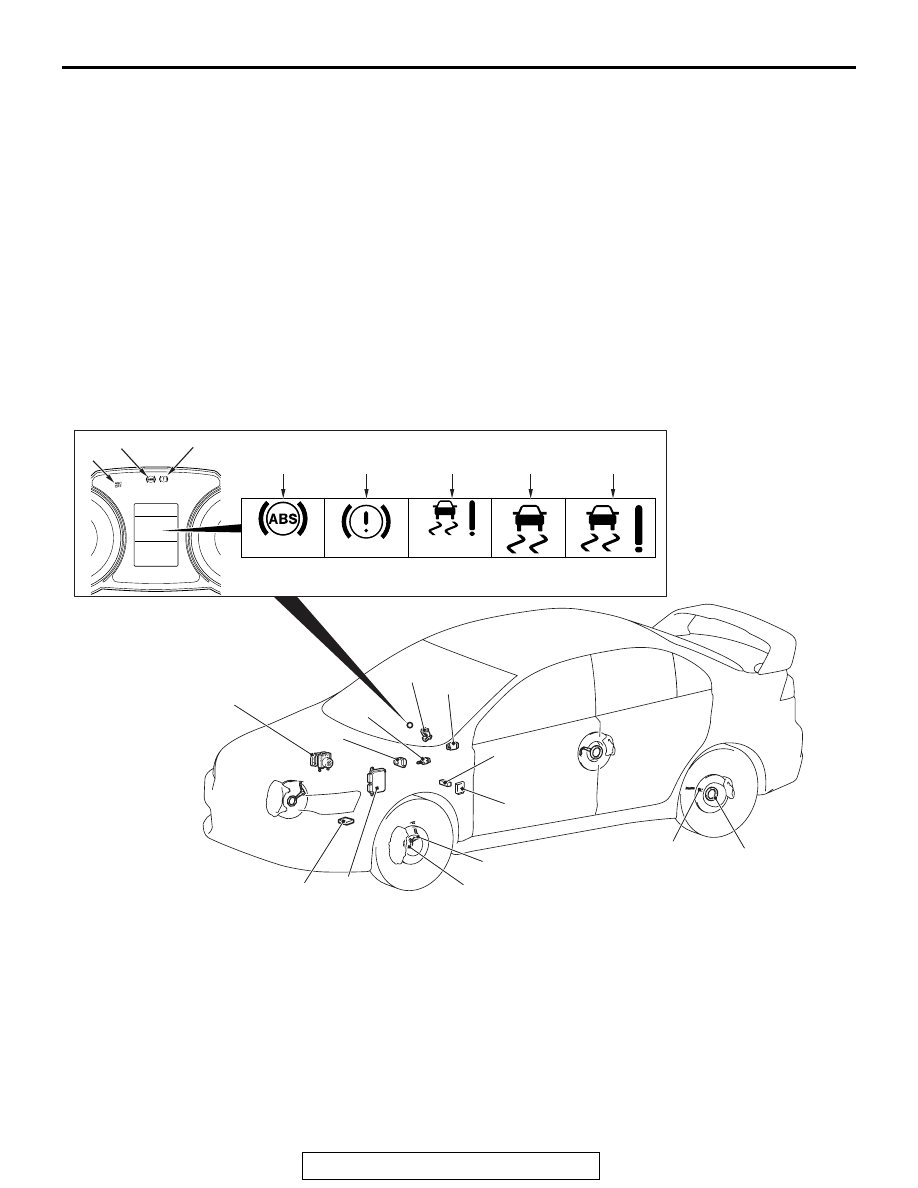
ACTIVE SAFETY

M2000031000959

ACTIVE SKID CONTROL SYSTEM (ASC)

AC709630

CHECK

SERVICE
         REQUIRED

SERVICE
         REQUIRED

AB

10

12

13

11

15

14

17

16

7, 8, 9, 22

19

20

5

3

4

6

18

21

1

2

1

2

TECHNICAL FEATURES

TSB Revision

GENERAL

00-15

MAIN COMPONENTS AND FUNCTIONS

.

Parts name

No. Functional description

Sensor

Wheel speed 
sensor

1

Outputs the frequency pulse signal in proportion to the rotation speed of 
each wheel to ASC-ECU.

Magnetic encoder 
for wheel speed 
detection

2

When the magnetic encoder for wheel speed detection (a plate on which 
north and south pole sides of the magnets are arranged alternately) 
rotates, the wheel speed sensor outputs frequency pulse signal in 
proportion to each wheel speed.

Stop light switch

3

Outputs the signal indicating whether the brake pedal is depressed or 
not to ASC-ECU.

G and yaw rate 
sensor

4

Detects the yaw rate and longitudinal/lateral acceleration of a vehicle, 
then outputs the signal to ASC-ECU via the CAN line.

Steering wheel 
sensor

5

Detects the steering angle of steering wheel, and outputs the signal to 
ASC-ECU via the CAN bus line.

Master cylinder 
pressure sensor

6

Integrated into the hydraulic unit, converts the signal of brake fluid 
pressure in master cylinder to the voltage value, then outputs the value 
to ASC-ECU.

Wheel cylinder 
pressure sensor

7

Integrated into the hydraulic unit, converts the signal of brake fluid 
pressure in wheel cylinder of each wheel to the voltage value, then 
outputs the value to ASC-ECU.

Actuator Hydraulic unit

8

Drives the solenoid valve using the signal from ASC-ECU, and controls 
the brake fluid pressure for each wheel.

ABS warning light 9

Informs the driver of the system status by illuminating, flashing, or 
turning off the warning light according to the signal from ASC-ECU.

ABS warning 
display

10

Informs the driver of the system status by illuminating or turning off the 
warning light according to the signal from ASC-ECU.

Brake warning 
light

11

Used as the warning light for the parking brake, brake fluid level, and 
EBD control. Informs the driver of the system status by illuminating or 
turning off the warning light according to the signal from ASC-ECU.

Brake warning 
display

12

Used as the warning light for the brake fluid level and EBD control. 
Informs the driver of the system status by illuminating or turning off the 
warning light according to the signal from ASC-ECU.

Data link connector

13

Outputs the diagnostic trouble code and establishes the communication 
with the scan tool.

ASC control unit (ASC-ECU) 14

Controls the actuators (described above) based on the signals coming 
from each sensors.
Controls the self-diagnostic functions and fail-safe functions.
Controls diagnostic function (Compatible with scan tool).

TECHNICAL FEATURES

TSB Revision

GENERAL

00-16

SYSTEM CONFIGURATION

The transaxle <twin clutch sportronic shift transmis-
sion (TC-SST) 

*1

> control and AWD <super all wheel 

control (S-AWC) 

*2

> control have been added to the 

conventional brake control and engine output control, 
and the controls are integrated. The vehicle stability 
has been improved with the equipped ASC.

• The ASC system integrates the traction control 

(TCL) function and skid control function.

• When TCL function detects the slip of driving 

wheel (for example, during startup on slippery 
road), it automatically applies the braking force to 
the slipping driving wheel. At the same time, TCL 
function reduces the engine output and prevents 
the wheel spin when it determines that the engine 
torque is too high for the road surface friction 
coefficient.

• When the skid control function determines that 

the vehicle is in a dangerous state, it reduces the 
engine output and applies brake force to four 
wheels independently to control the vehicle 
behavior, avoiding the critical state.

• Brake performance at ASC system failure is 

ensured by the fail-safe function, and at the same 
time, the serviceability during service is 
improved.

NOTE: 

.

*1

: For the details on twin clutch sportronic shift 

transmission (TC-SST), refer to GROUP 22B 


Twin Clutch Sportronic Shift Transmission 
(TC-SST) 

P.22B-2

.

*2

: For the details on super all wheel control 

(S-AWC), refer to GROUP 22B 

 Super All Wheel 

Control (S-AWC) 

P.22B-18

.

The active skid control (ASC) has the traction 
control function and the skid control function. By 
the integrated control with the anti-lock brake 
system, the system stabilizes the vehicle attitude 
and, at the same time, secures the driving force.

FOUR-WHEEL ANTI-LOCK BRAKE 
SYSTEM (4 ABS)

The ABS (with EBD and brake assist) that ensures 
directional stability and controllability during hard 
braking has been equipped to GSR.
This ABS employs a 4-sensor system that indepen-
dently controls the right and left wheels of front and 
rear, and has the following features:

• EBD 

*1

 (Electronic Brake-force Distribution sys-

tem) control that can provide ideal rear wheel 
brake force has been employed.

• The magnetic encoder for wheel speed detection 

has been installed instead of the rotor as the 
wheel speed sensor.

AC704103

ASC OFF switch

G&yaw rate sensor

Engine ECU

S-AWC-ECU

TC-SST-ECU

ASC-ECU

ETACS-ECU

AB

Local CAN

CAN-C

CAN-B

Stop light switch

Combination meter

Steering wheel sensor

Wheel
speed
sensor
(RR)

Wheel
speed
sensor
(RL)

Wheel speed
sensor (FL)

Wheel speed
sensor (FR)

TECHNICAL FEATURES

TSB Revision

GENERAL

00-17

• For wiring harness saving and secure data com-

munication, CAN 

*2

 bus has been adopted as a 

tool of communication with another ECU.

NOTE: 

.

*1

: EBD (Electronic Brake-force Distribution)

*2

: For more details on CAN (Controller Area Net-

work), refer to GROUP 54C 

P.54C-2

.

As with the active skid control (ASC), ABS is con-
trolled by ASC-ECU.

PASSIVE SAFETY

M2000032001041

IMPACT SAFETY BODY RISE (REINFORCED IMPACT SAFETY EVOLUTION)

AB700981

A

1

3

2

4

AB

B

AB700984AB

C

D

D

5

6


Content   ..  64  65  66  67   ..