Mitsubishi Lancer Evolution X. Manual - part 628


  Index      Mitsubishi     Mitsubishi Lancer Evolution X GS41EVO - service repair manual 2008 year


Search            


Content   ..  626  627  628  629   ..


Mitsubishi Lancer Evolution X. Manual - part 628


INPUT SHAFT

TSB Revision

MANUAL TRANSAXLE OVERHAUL

22B-25

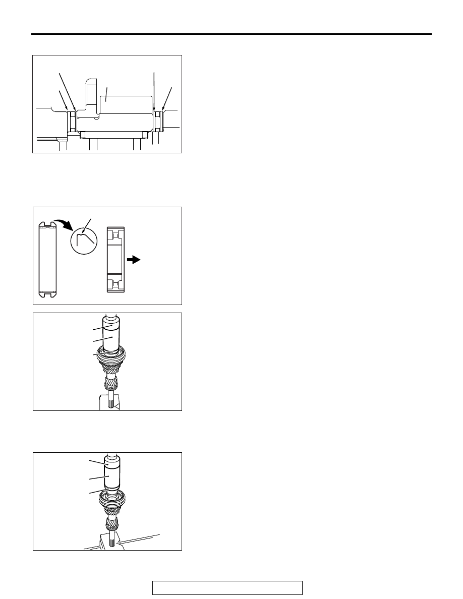
>>B<< THRUST BEARING INSTALLATION

Install the thrust bearings as shown.

.

>>C<< 3RD-4TH SPEED SYNCHRONIZER HUB / 
3RD-4TH SPEED SYNCHRONIZER SLEEVE 
INSTALLATION

1. Install the 3rd-4th speed synchronizer hub and synchronizer 

sleeve in the illustrated direction.

2.  Using the special tools, MD998812, MD998813 and 

MD998822, indicated below, install the 3rd-4th speed 
synchronizer sleeve, 3rd-4th speed synchronizer hub, 
synchronizer outer ring, synchronizer inner ring and 
synchronizer cone.

3. After installation, check that the 3rd speed gear rotates 

smoothly.

.

>>D<< 4TH SPEED GEAR SLEEVE 
INSTALLATION

Using the special tools, MD998812, MD998813 and 
MD998822, indicated below, install the 4th speed gear sleeve.

.

AK703374AC

(thick)

3rd speed gear

(thin)

Black

Colorless

(thin)

Colorless

(thick)

Black

AK703159

Identification groove

Installation
direction

AC

AK703169

AC

MD998812

MD998813

MD998822

AK703170

AC

MD998812

MD998813

MD998822

INPUT SHAFT

TSB Revision

MANUAL TRANSAXLE OVERHAUL

22B-26

>>E<< 5TH SPEED GEAR SLEEVE INSTALLATION

Using the special tools, MD998812, MD998813 and 
MD998822, indicated below, install the 5th speed gear sleeve.

.

>>F<< 5TH SPEED SYNCHRONIZER HUB / 5TH 
SYNCHRONIZER SLEEVE INSTALLATION

1. Install the 5th speed synchronizer hub and synchronizer 

sleeve in the illustrated direction.

2. Using the special tools, MD998812, MD998813 and 

MD998822, indicated below, install the 5th speed 
synchronizer hub and synchronizer sleeve.

3. After installation, check that the 5th speed gear rotates 

smoothly.

.

>>G<< TAPER ROLLER BEARING INSTALLATION

Using the special tools, MD998812, MD998813 and 
MD998822, indicated below, press-fit the taper roller bearing.

.

AK703171

AC

MD998812

MD998813

MD998822

AK703158

Identification
groove

Identification
groove

Installation
direction

AC

AK703172

AC

MD998812

MD998813

MD998822

AK703173

AC

MD998812

MD998822

MD998813

INPUT SHAFT

TSB Revision

MANUAL TRANSAXLE OVERHAUL

22B-27

>>H<< SNAP RING INSTALLATION

Select and install appropriate snap ring onto the input shaft so 
that the clearance of the taper roller bearing meets the stan-
dard value.

Standard value: 0.01  0.09 mm (0.0004  0.0035 inch)

.

>>I<< OIL SEAL INSTALLATION

Using special tool, MD999601, drive the oil seal as deep as 
shown into place.

INSPECTION

M1222001700330

.

INPUT SHAFT

• Check the needle bearing mounting portion of the shaft for 

damage, wear and seizure.

• Check the splines for damage and wear.

.

AK703174

AK702519

AH

3.5 mm
(0.14 inch)

Oil seal

AK703175AC

MD999601

AK702517AC

INPUT SHAFT

TSB Revision

MANUAL TRANSAXLE OVERHAUL

22B-28

NEEDLE BEARING

• Combine the needle bearing with the input shaft and gears 

and check that it smoothly rotates without noise or play.

• Check the needle bearing retaining sleeve for deformation.

.

SPEED GEARS

1. Check that the helical and clutch gears of each speed gear 

are not damaged or worn in the tooth surface.

2. Check that the synchronizer cone of each speed gear is not 

roughened, damaged or worn in the surface.

3. Check that the inner, front and rear surfaces of each speed 

gear are not damaged or worn.

.

SYNCHRONIZER RING

1. Check that the outer synchronizer ring clutch gear is free of 

damage.

2. Check that the synchronizer rings and synchronizer cones 

are free of damage or wear in the contact surface and 
broken screw threads.

3. Check that the outer synchronizer ring and synchronizer key 

contact surface is free of damage and wear.

4. Join the outer and inner synchronizer rings and synchronizer 

cone together and check clearance "A" shown. If "A" is less 
than the limit value, replace them.

Limit A (from back of outer ring to clutch gear): 0.5 

mm (0.02 inch)

.

SYNCHRONIZER SLEEVE AND HUB

• Combine the synchronizer sleeve and hub, and check that 

they slide smoothly.

• Check that the sleeve is free of damage at its inside spline 

ends.

AK204169AD

AK703376AC

AK703161

AC

Gear

Cone

Outer ring

Inner ring

A

AK703375


Content   ..  626  627  628  629   ..