Mitsubishi Lancer Evolution X. Manual - part 619
PADDLE SHIFT ASSEMBLY
TSB Revision
TWIN CLUTCH- SPORTRONIC SHIFT TRANSMISSION (TC-SST)
22C-433
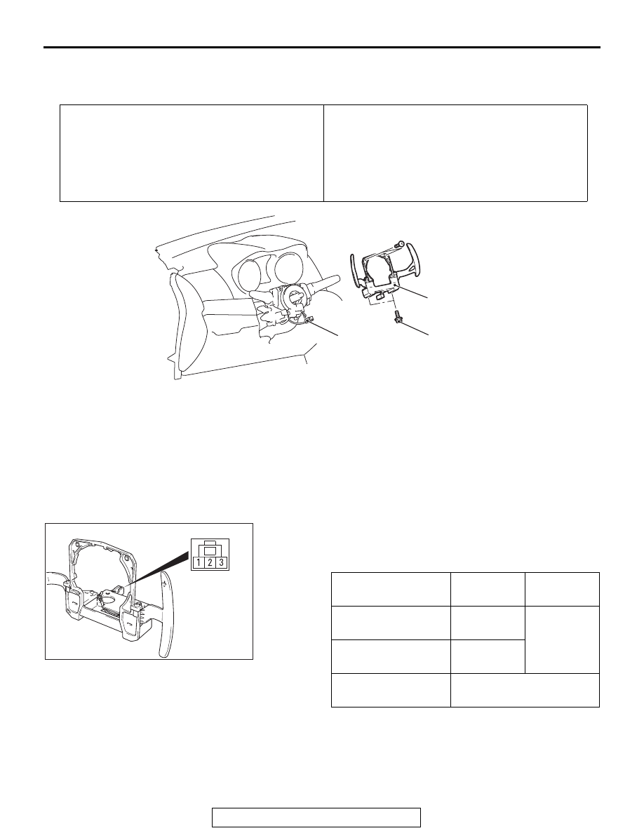
PADDLE SHIFT ASSEMBLY
REMOVAL AND INSTALLATION
M1225010600017
INSPECTION
PADDLE SHIFT SWITCH CHECK
M1225011300019
1. Check the continuity between the paddle shift switch
connector terminals.
Standard value:
2. In the cases other than the above, replace the paddle shift
assembly.
Pre-removal Operation
• Steering wheel assembly and driver's air bag module
removal (Refer to GROUP 37 − Steering Wheel
• Steering column lower cover and steering column upper
cover removal (Refer to GROUP 37 − Steering Shaft
Post-installation Operation
• Steering column lower cover and steering column upper
cover installation (Refer to GROUP 37 − Steering Shaft
• Steering wheel assembly and driver's air bag module
installation (Refer to GROUP 37 − Steering Wheel
• Steering wheel at straight-ahead position check
AC710518 AB
7.0 ± 3.0 N·m
62 ± 26 in-lb
1
2
Removal steps
1. Paddle shift switch connector
connection
2. Paddle shift assembly
Paddle shift lever
Terminal
number
Resistance
value
Upshift and hold the
lever.
1 − 2
Continuity
exists. (2 Ω
or less)
Downshift and hold
the lever.
2 − 3
No operation
No continuity between the
terminals
AC507715AC