Mitsubishi Lancer Evolution X. Manual - part 602


  Index      Mitsubishi     Mitsubishi Lancer Evolution X GS41EVO - service repair manual 2008 year


Search            


Content   ..  600  601  602  603   ..


Mitsubishi Lancer Evolution X. Manual - part 602


DIAGNOSIS <TC-SST>

TSB Revision

TWIN CLUTCH- SPORTRONIC SHIFT TRANSMISSION (TC-SST)

22C-365

SPECIAL FUNCTION

M1225028400052

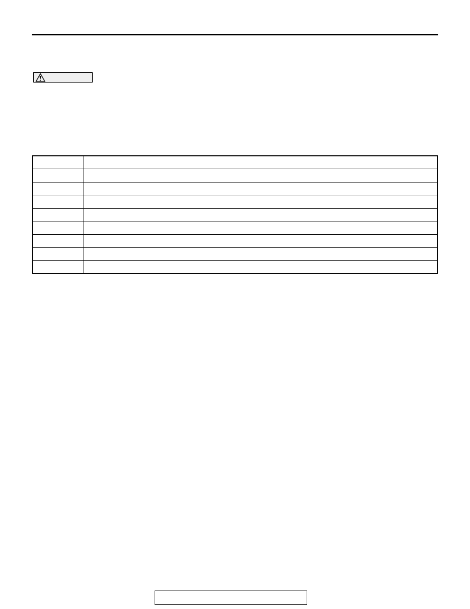
TEACH-IN REFERENCE TABLE

CAUTION

Be careful with the following items when performing Item No.3: Line Pressure Test.

• The engine speed could be high (4,000 r/min) when the Line Pressure Test is in progress. (Depend-

ing on the transaxle state, the engine speed may not be high.)

• After Teach-In completion, check that it completed normally. (Teach-In execution results is dis-

played in the following Data list.)

TEACH-IN

NOTE: 

.

According to the transmission fluid state (fluid -filled state), Teach-In executed time is not equal.

Item No.8 is not displayed when the Diag. Version of TC-SST-ECU is pre-0002. (Diag. Version can be 
checked by the Teach-In screen of scan tool.)

Item No.

Scan tool Item Name

1

Plausibility check

2

Shift fork Teach-In

3

Line pressure Test

4

Stroke Teach-In

5

Boost Teach-In

6

Interlock Teach-In

7

Clutch Ventilation

8

Reset clutch gain

DIAGNOSIS <TC-SST>

TSB Revision

TWIN CLUTCH- SPORTRONIC SHIFT TRANSMISSION (TC-SST)

22C-366

DATA LIST

TC-SST-ECU TERMINAL VOLTAGE REFERENCE CHART

M1225006800018

No.

Data List Item Name Teach-In state or result

Scan tool display

100 Teach-In executing

Before execution

No

Other than the execution 
conditions

Pending

After execution

Yes → No

101 Normal End

At the normal end

Yes

At the abnormal end

No

102 Abnormal End

At the normal end

No

At the abnormal end

Yes

103 Timeout error

When a timeout error is not 
occurred

No

When a timeout error is 
occurred

Yes

104 Abort conditions error When an error other than the 

execution conditions is not 
occurred

No

When an error other than the 
execution conditions is occurred

Yes

110

Execute last Teach-In 
item

The previously conducted scan tool item 
name is displayed

111

Internal Error Data

The monitoring unit No. is displayed in case 
of an error

AC707707

B-107

AC

Terminal 
No.

Check items

Check conditions

Standard value

2

CAN_L

5

CAN_H

6

Back-up power supply

Always

Battery positive 
voltage

11

Power supply

Ignition switch: ON

Battery positive 
voltage

Ignition switch: OFF

1 V or less

17

LIN

19

Ground

Always

1 V or less

DIAGNOSIS <SHIFT LEVER>

TSB Revision

TWIN CLUTCH- SPORTRONIC SHIFT TRANSMISSION (TC-SST)

22C-367

DIAGNOSIS <SHIFT LEVER>

INTRODUCTION

M1225024900022

The shift lever can exhibit any of the following symp-
toms: Impossible to move, or does not work.

The causes of these symptoms could come from: 
incorrect mounting or a component of the shift lever 
may be faulty.

TROUBLESHOOTING STRATEGY

M1225007900029

Use these steps to plan your diagnostic strategy. If 
you follow them carefully, you will find most shift lever 
malfunctions.
1. Gather as much information as possible about the 

complaint from the customer.

2. Verify that the condition described by the 

customer exists.

3. Check the vehicle for any shift lever Diagnostic 

Trouble Codes (DTCs).

4. If you cannot verify the condition and there are no 

DTCs, the malfunction is intermittent. For 
information on how to cope with intermittent 
malfunctions, refer to GROUP 00, How to Use 
Troubleshooting/Inspection Service Points − How 

to Cope with Intermittent Malfunction 

P.00-15

.

5. If you can verify the condition but there are no 

DTCs, or the system cannot communicate with 
scan tool, refer to the Symptom Chart 

P.22C-370

.

6. If there is a DTC, record the number of the code, 

then erase the code from memory using scan tool.

7. Reconfirm the symptom.
8. If a DTC is set again, go to the Inspection Chart 

for Diagnostic Trouble Codes.

9. If a DTC is not set again, the malfunction is 

intermittent. For information on how to cope with 
intermittent malfunctions, refer to GROUP 00, 
How to Use Troubleshooting/Inspection Service 
Points − How to Cope with Intermittent Malfunction 

P.00-15

.

10.Verify malfunction is eliminated. After repairs are 

completed, the complaint conditions to confirm 
the malfunction has been eliminated.

DIAGNOSIS FUNCTION

M1225000500020

WARNING INDICATOR

When a malfunction occurs to the shift lever, the figure (A) 
remains displayed on the information screen of multi informa-
tion display.
If the figure (A) remains displayed on the information screen of 
multi information display, check whether or not a diagnostic 
trouble code is set.

FAIL-SAFE FUNCTION

If an abnormality occurs to the signal of sensors, 
switches, solenoids, or others, the shift lever-ECU 
performs a control for the driver safety and system 
protection. The control contents are as follows.

AC710447AD

(A)

SERVICE

           REQUIRED

DIAGNOSIS <SHIFT LEVER>

TSB Revision

TWIN CLUTCH- SPORTRONIC SHIFT TRANSMISSION (TC-SST)

22C-368

FAIL-SAFE REFERENCE TABLE

HOW TO CONNECT THE SCAN TOOL (M.U.T.-III)

Required Special Tools:

• MB991958 Scan Tool (M.U.T.-III Sub Assembly)

• MB991824: Vehicle Communication Interface (V.C.I.)
• MB991827 M.U.T.-III USB Cable
• MB991910 M.U.T.-III Main Harness A (Vehicles with 

CAN communication system)

CAUTION

To prevent damage to scan tool MB991958, always turn the 
ignition switch to the "LOCK" (OFF) position before con-
necting or disconnecting scan tool MB991958.
1. Ensure that the ignition switch is at the "LOCK" (OFF) 

position.

2. Start up the personal computer.
3. Connect special tool MB991827 to special tool MB991824 

and the personal computer.

4. Connect special tool MB991910 to special tool MB991824.
5. Connect special tool MB991910 to the data link connector.
6. Turn the power switch of special tool MB991824 to the "ON" 

position.
NOTE: When special tool MB991824 is energized, special 
tool MB991824 indicator light will be illuminated in a green 
color.

7. Start the scan tool system on the personal computer.
NOTE: Disconnecting scan tool MB991958 is the reverse of the 
connecting sequence, making sure that the ignition switch is at 
the "LOCK" (OFF) position.

Code No.

Item

Control content

P198D

EEPROM

Normal driving can be performed, and displays an occurrence of 
trouble to the multi information display to warn the driver.

P198E

Lever position sensor 
system (Malfunction of 
one sensor)

Normal driving can be performed, and displays an occurrence of 
trouble to the multi information display to warn the driver.

P198F

Lever position sensor 
system (Malfunction of 
two sensors)

The lever position cannot be identified, and the clutch open at TC-SST 
side prohibits the vehicle from driving. Then displays an occurrence of 
trouble to the multi information display to warn the driver.

AC608435

Data link connector

MB991827

MB991824

MB991910

AB


Content   ..  600  601  602  603   ..