Mitsubishi Lancer Evolution X. Manual - part 590


  Index      Mitsubishi     Mitsubishi Lancer Evolution X GS41EVO - service repair manual 2008 year


Search            


Content   ..  588  589  590  591   ..


Mitsubishi Lancer Evolution X. Manual - part 590


DIAGNOSIS <TC-SST>

TSB Revision

TWIN CLUTCH- SPORTRONIC SHIFT TRANSMISSION (TC-SST)

22C-317

.

OBD-II DRIVE CYCLE PATTERN 
<RATIONALITY>

Each value of failure condition 1 or failure condition 2 
(Logic Flow Charts (Monitor Sequence) <Rational-
ity>) returns to the normal value and remains in the 
state for 500 milliseconds.

.

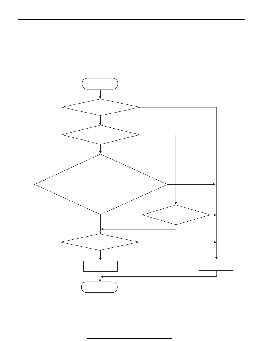
LOGIC FLOW CHARTS (Monitor Sequence) <Rationality - plausibility failure>

.

AC710601

No

Yes

Malfunction

No

Yes

Monitoring condition met

No

Yes

Yes

Engine speed signal
status = not SNA

Continuous failure
for 250 msec

Input shaft speed*

1

> 12,800 r/min

START

END

Yes

|Input shaft speed*

1

| > (min(max(engine speed, 

input shaft target speed [current gear]*

1

,

input shaft target speed [target gear]*

1

) + 3,000 r/min,

12,800 r/min)

Good

No

No

*

1

 :In case of input shaft 1 (odd) speed sensor monitor, this is speed of input shaft (odd).

    In case of input shaft 2 (even) speed sensor monitor, this is speed of input shaft (even).

DIAGNOSIS <TC-SST>

TSB Revision

TWIN CLUTCH- SPORTRONIC SHIFT TRANSMISSION (TC-SST)

22C-318

DTC SET CONDITIONS

Check Conditions <Rationality plausibility fail-

ure>

• Voltage of battery: 8 V or more.
• Voltage of battery: 16.5 V or less.

JUDGMENT CRITERIA <Rationality plausibility 

failure>

• Input shaft 2 (even) speed: Refer to Logic Flow 

Charts (Monitor Sequence) <Rationality plausibil-
ity failure>. (250 millisecond)

.

OBD-II DRIVE CYCLE PATTERN 
<RATIONALITY PLAUSIBILITY FAILURE>

The value of the Logic Flow Charts (Monitor 
Sequence) <Rationality plausibility failure> returns to 
the normal value and remains in the state for 250 mil-
liseconds.

.

PROBABLE CAUSES

• Malfunction of TC-SST-ECU

DIAGNOSTIC PROCEDURE

Required Special Tools:

• MB991958 Scan Tool (M.U.T.-III Sub Assembly)

• MB991824: Vehicle Communication Interface (V.C.I.)
• MB991827 M.U.T.-III USB Cable
• MB991910 M.U.T.-III Main Harness A

STEP 1. Scan tool CAN bus diagnostics
Using scan tool MB991958, diagnose the CAN bus lines.
Q: Is the check result normal?

YES : Go to Step 2.
NO :  Repair the CAN bus lines. (Refer to GROUP 54C − 

Troubleshooting 

P.54C-15

.) After repairing the CAN 

bus line, go to Step 2.

STEP 2. Monitoring unit No. check
(1) Check the freeze frame data (item No. 30 to No. 37).
(2) Check which monitoring unit (No. 115 or No. 240) is set.
Q: Which monitoring unit is set, No. 115 or No. 240?

No. 115 : Go to Step 4
No. 240 : Go to Step 3

STEP 3. Check whether the DTC is reset.
(1) Erase the DTC.
(2) Drive the vehicle at 50 km/h (31 mph) or more.
(3) Check that the DTC is reset.
Q: Is DTC No.P2766 set?

YES : Replace the mechatronic assembly. (Refer to 

P.22C-421

.)

NO :  Intermittent malfunction. (Refer to GROUP 00 − How 

to Cope with Intermittent Malfunction 

P.00-15

.)

DIAGNOSIS <TC-SST>

TSB Revision

TWIN CLUTCH- SPORTRONIC SHIFT TRANSMISSION (TC-SST)

22C-319

STEP 4. Check whether the DTC is reset.
(1) Erase the DTC.
(2) Drive with shifting to each gear range.
(3) Check that the DTC is reset.
Q: Is DTC No.P2766 set?

YES : Go to Step 5.
NO :  Intermittent malfunction. (Refer to GROUP 00 − How 

to Cope with Intermittent Malfunction 

P.00-15

.)

STEP 5. Scan tool Teach-In
(1) Carry out the Item No. 1: Plausibility check. (Refer to 

Special Function (Teach-In Reference Table 

P.22C-365

).) 

(2) After Teach-In, check which result ("Yes" or "No") is 

displayed in the Data list No. 101: Normal End. (Refer to 
Special Function (Teach-In Reference Table 

P.22C-365

).)

Q: Which is displayed, "Yes" or "No"?

"Yes" : Replace the transaxle assembly. (Refer to 

P.22C-412

.)

"No" : Replace the mechatronic assembly. (Refer to 

P.22C-421

.)

DTC P2809: Clutch/Shift Switching Solenoid 2, spool stuck

CAUTION

• If there is any problem in the CAN bus lines, 

an incorrect diagnostic trouble code may be 
set. Prior to this diagnosis, diagnose the CAN 
bus lines.

• Whenever the ECU is replaced, ensure that 

the CAN bus lines are normal.

.

DIAGNOSTIC FUNCTION

TC-SST-ECU checks that the clutch/shift switching 
solenoid 2 is normal.

.

DESCRIPTIONS OF MONITOR METHODS

The clutch/shift switching solenoid 2 is determined to 
be seized.

.

MONITOR EXECUTION

• Continuous

.

MONITOR EXECUTION CONDITIONS 
(OTHER MONITOR AND SENSOR)

Other Monitor (There is no temporary DTC stored 

in memory for the item monitored below)

• P2733: Clutch/shift switching solenoid 1, spool 

stuck

• P2736: Clutch/shift switching solenoid 1 system 

(Open circuit)

• P2738: Clutch/shift switching solenoid 1 system 

(Short to ground)

• P2739: Clutch/shift switching solenoid 1 system 

(Short to power supply)

• P2812: Clutch/shift switching solenoid 2 system 

(Open circuit)

• P2814: Clutch/shift switching solenoid 2 system 

(Short to ground)

• P2815: Clutch/shift switching solenoid 2 system 

(Short to power supply)

• P181E: Clutch 2 (Pressure low range out)
• P181F: Clutch 2 (Pressure high range out)

Sensor (The sensor below is determined to be 

normal)

• Clutch/shift switching solenoid 1

.

DIAGNOSIS <TC-SST>

TSB Revision

TWIN CLUTCH- SPORTRONIC SHIFT TRANSMISSION (TC-SST)

22C-320

LOGIC FLOW CHARTS (Monitor Sequence)

.

DTC SET CONDITIONS

Check Conditions

• Voltage of battery: 8 V or more.
• Voltage of battery: 16.5 V or less.
• Engine speed: 650 r/min or more.
• Time since above engine condition: 1.5 seconds 

or more.

• Clutch/shift switching solenoid 2: ON.
• Clutch cooling flow solenoid: OFF.
• Clutch/shift pressure solenoid 2: ON.

JUDGMENT CRITERIA

• Clutch 2 (even) pressure: 1,400 hPa or more, or 

clutch 2 pressure sensor (even) change: 0, and 
shift fork position sensor 3 and 4 change: 0. (200 
millisecond)

.

OBD-II DRIVE CYCLE PATTERN

The status with the clutch 2 pressure 1,400 hPa or 
less, or with the clutch 2 pressure sensor (even) and 
shift fork position sensor 3 and 4 changed continues 
for 200 millisecond.

.

PROBABLE CAUSES

• Malfunction of TC-SST-ECU
• Insufficient fluid level
• Malfunction of clutch/shift switching solenoid 2

AC710660

START

No

Good

Malfunction

END

Continuous failure
for 200 msec

No

Yes

Yes

Yes

No

Monitoring condition met

Clutch pressure
> 1,400 mbar

Yes

Yes

No

No

Clutch pressure
sensor change = 0

|Shift fork position
sensor change| = 0

hPa

AB


Content   ..  588  589  590  591   ..