Mitsubishi Lancer Evolution X. Manual - part 583
DIAGNOSIS <TC-SST>
TSB Revision
TWIN CLUTCH- SPORTRONIC SHIFT TRANSMISSION (TC-SST)
22C-289
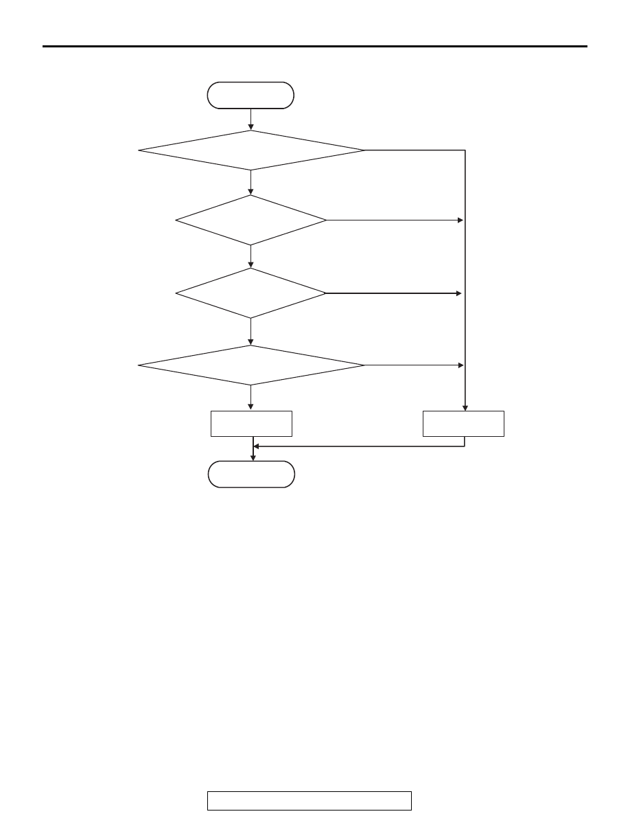
LOGIC FLOW CHARTS (Monitor Sequence)
.
DTC SET CONDITIONS
Check Conditions
• Voltage of battery: 8 V or more.
• Voltage of battery: 16.5 V or less.
JUDGMENT CRITERIA
• FET (Field Effect Transistor) current: 3.5 A or
more, and FET (Field Effect Transistor) output:
100 mV or less. (300 millisecond)
.
OBD-II DRIVE CYCLE PATTERN
The status with the current of the FET channel shunt
3.5 A or less and with the FET channel output 100
mV or more continues for 300 milliseconds.
.
PROBABLE CAUSES
• Malfunction of TC-SST-ECU
• Malfunction of clutch/shift pressure solenoid 1
DIAGNOSTIC PROCEDURE
Required Special Tools:
• MB991958 Scan Tool (M.U.T.-III Sub Assembly)
• MB991824: Vehicle Communication Interface (V.C.I.)
• MB991827 M.U.T.-III USB Cable
• MB991910 M.U.T.-III Main Harness A
AC710657
START
No
Yes
Good
Malfunction
END
Monitoring condition met
Continuous failure
for 300 msec
No
Yes
No
Yes
Yes
FET* output < 100 mV
FET* current > 3.5 A
No
*FET : Field Effect Transistor