Mitsubishi Lancer Evolution X. Manual - part 574
DIAGNOSIS <TC-SST>
TSB Revision
TWIN CLUTCH- SPORTRONIC SHIFT TRANSMISSION (TC-SST)
22C-253
• P2728: Clutch/shift pressure solenoid 2 system
(Overcurrent)
• P2729: Clutch/shift pressure solenoid 2 system
(Short to ground)
• P2730: Clutch/shift pressure solenoid 2 system
(Short to power supply)
• P2809: Clutch/shift switching solenoid 2, spool
stuck
• P2812: Clutch/shift switching solenoid 2 system
(Open circuit)
• P2814: Clutch/shift switching solenoid 2 system
(Short to ground)
• P2815: Clutch/shift switching solenoid 2 system
(Short to power supply)
• P181B: Clutch 1 (Pressure low range out)
• P181C: Clutch 1 (Pressure high range out)
• P181E: Clutch 2 (Pressure low range out)
• P181F: Clutch 2 (Pressure high range out)
Sensor (The sensor below is determined to be
normal)
• Shift select solenoid 1
• Clutch/shift pressure solenoid 2
• Clutch/shift switching solenoid 2
.
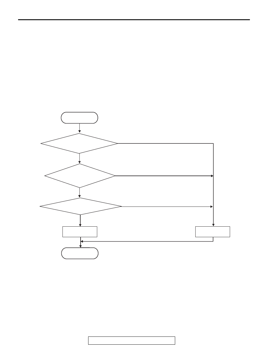
LOGIC FLOW CHARTS (Monitor Sequence)
.
DTC SET CONDITIONS
Check Conditions
• Voltage of battery: 8 V or more.
• Voltage of battery: 16.5 V or less.
• Engine speed: 650 r/min or more.
• Time since above engine condition: 1.5 seconds
or more.
• FET (Field Effect Transistor) of high side 3:
Switched off.
JUDGMENT CRITERIA
• FET output: 100 mV or less. (5 seconds)
.
OBD-II DRIVE CYCLE PATTERN
The FET channel output remains 100 mV or more for
5 seconds.
.
PROBABLE CAUSES
• Malfunction of TC-SST-ECU
• Malfunction of power supply circuit (open circuit)
AC710728
START
No
Good
Malfunction
END
Continuous failure
for 5 sec
No
Yes
Yes
Monitoring condition met
Yes
No
FET* output < 100 mV
*FET : Field Effect Transistor