Mitsubishi Lancer Evolution X. Manual - part 546
DIAGNOSIS <TC-SST>
TSB Revision
TWIN CLUTCH- SPORTRONIC SHIFT TRANSMISSION (TC-SST)
22C-141
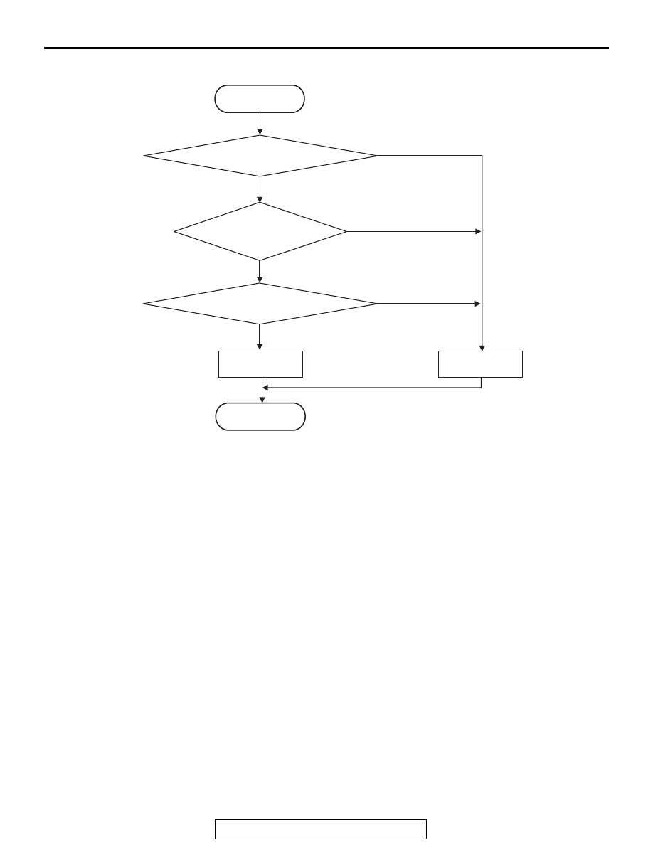
LOGIC FLOW CHARTS (Monitor Sequence)
.
DTC SET CONDITIONS
Check Conditions
• Voltage of battery: 8 V or more.
• Voltage of battery: 16.5 V or less.
• Engine speed: 650 r/min or more.
• Time since above engine condition: 1.5 seconds
or more.
• Input shaft 1 (odd) speed: 500 r/min or more.
• Input shaft 2 (even) speed: 500 r/min or more.
• Shift fork 1 position: Neutral.
• Input shaft 2 (even) gear: Engaged.
• Engine speed − input shaft 2 speed: 50 r/min or
less.
JUDGMENT CRITERIA
• Calculated speed: 40 r/min or less. (500 millisec-
ond)
.
OBD-II DRIVE CYCLE PATTERN
The calculated speed remains 40 r/min or more for
500 millisecond.
.
PROBABLE CAUSES
• Malfunction of TC-SST-ECU
• Malfunction of shift fork position sensor 1
DIAGNOSTIC PROCEDURE
Required Special Tools:
• MB991958 Scan Tool (M.U.T.-III Sub Assembly)
• MB991824: Vehicle Communication Interface (V.C.I.)
• MB991827 M.U.T.-III USB Cable
• MB991910 M.U.T.-III Main Harness A
AC711383
START
No
Good
Malfunction
END
Monitoring condition met
Continuous failure
for 500 msec
No
Yes
Yes
Yes
No
Calculated input
shaft speed
AC
Calculated input shaft
speed <= 40 r/min