Mitsubishi Lancer Evolution X. Manual - part 522
DIAGNOSIS <TC-SST>
TSB Revision
TWIN CLUTCH- SPORTRONIC SHIFT TRANSMISSION (TC-SST)
22C-45
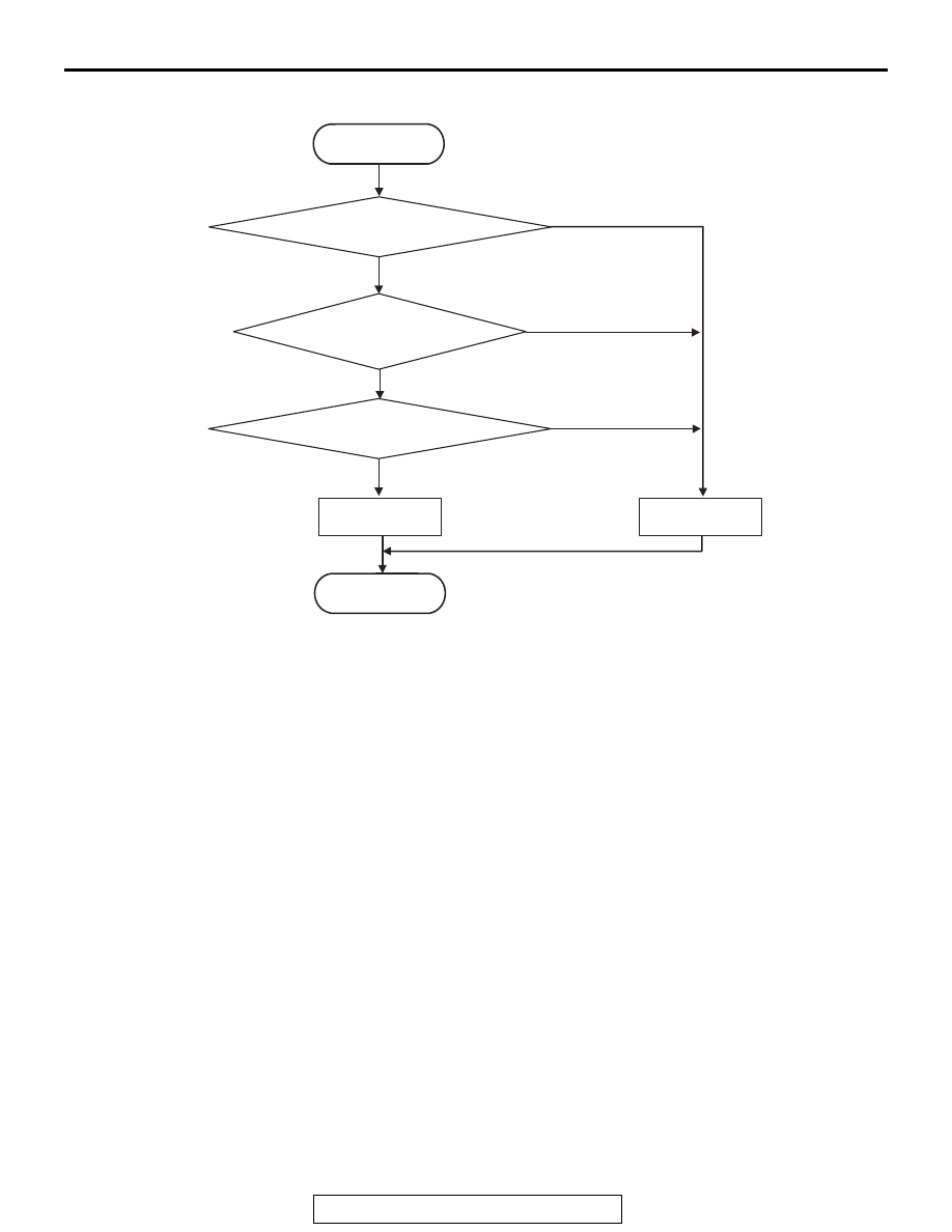
LOGIC FLOW CHARTS (Monitor Sequence)
.
DTC SET CONDITIONS
Check Conditions
• Voltage of battery: 8 V or more.
• Voltage of battery: 16.5 V or less.
• Engine speed: 650 r/min or more.
• Time since above engine condition: 1.5 seconds
or more.
JUDGMENT CRITERIA <Rationality-high>
• Calculated current (actual current − target cur-
rent): 1,000 mA or more. (1 second)
JUDGMENT CRITERIA <Rationality-low>
• Calculated current (target current − actual cur-
rent): 1,000 mA or more. (1 second)
.
OBD-II DRIVE CYCLE PATTERN
<RATIONALITY-HIGH>
The value of the calculated current (actual current −
target current) remains 1,000 mA or less for 1 sec-
ond.
.
OBD-II DRIVE CYCLE PATTERN
<RATIONALITY-LOW>
The value of the calculated current (target current −
actual current) remains 1,000 mA or less for 1 sec-
ond.
.
PROBABLE CAUSES
• Malfunction of TC-SST-ECU
• Malfunction of clutch cooling flow solenoid
DIAGNOSTIC PROCEDURE
Required Special Tools:
• MB991958 Scan Tool (M.U.T.-III Sub Assembly)
• MB991824: Vehicle Communication Interface (V.C.I.)
• MB991827 M.U.T.-III USB Cable
• MB991910 M.U.T.-III Main Harness A
AC710633
START
No
Yes
Good
Malfunction
END
Monitoring condition met
Continuous failure
for 1 sec
No
Yes
Yes
No
Calculated current
> 1,000 mA