Mitsubishi Lancer Evolution X. Manual - part 513


  Index      Mitsubishi     Mitsubishi Lancer Evolution X GS41EVO - service repair manual 2008 year


Search            


Content   ..  511  512  513  514   ..


Mitsubishi Lancer Evolution X. Manual - part 513


DIAGNOSIS <TC-SST>

TSB Revision

TWIN CLUTCH- SPORTRONIC SHIFT TRANSMISSION (TC-SST)

22C-9

<MECHATRONIC ASSEMBLY REPLACEMENT>

<CLUTCH ASSEMBLY REPLACEMENT>
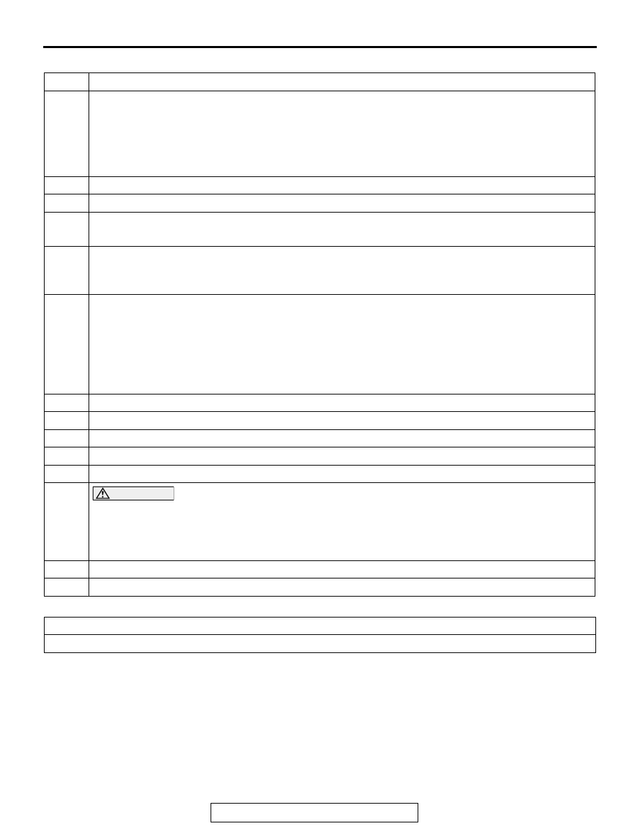
Steps

Contents

1

With the scan tool connected and the vehicle set to the condition below, execute the Teach-In. 

• Engine: Idling
• Shift lever position: P range
• Brake pedal: Depressed
• Parking brake: Pulled
• Transmission fluid temperature: 40° C to 80° C (104° F to 176° F)

2

Select "Special Function" of TC-SST.

3

Select "Teach-In" of Special Function.

4

According to "2-2 Item execution order", select the Item No.7: Clutch Ventilation to execute.
NOTE: Before execution, "No" is displayed in the Data list No. 100: Teach-In executing.

5

After execution, check that "Yes" is displayed in the Data list No. 100: Teach-In executing. 
NOTE: In a case other than the execution conditions, "Pending" is displayed in the Data list No. 
100: Teach-In executing.

6

After the Teach-In (Item No. 7: Clutch Ventilation) completion, check that "No" is displayed in the 
Data list No. 100: Teach-In executing and execution results are displayed in the Data list No. 101 to 
No. 104.

• No.101: Normal End: On normal end, "Yes" is displayed.
• No.102: Abnormal End: On abnormal end, "Yes" is displayed.
• No.103: Timeout error: On timeout error, "Yes" is displayed.
• No.104: Abort conditions error: In a case other than the execution conditions, "Yes" is displayed.

7

Change the item to No. 1: Plausibility check, and execute steps from 4 to 6 in the same manner.

8

Change the item to No. 2: Shift fork Teach-In, and execute steps from 4 to 6 in the same manner.

9

Turn the ignition switch to the LOCK (OFF) position.

10

Change the item to No. 7: Clutch Ventilation, and execute steps from 4 to 6 in the same manner.

11

Change the item to No. 4: Stroke Teach-In, and execute steps from 4 to 6 in the same manner.

12

CAUTION

Be careful with the following item when performing Item No.5: Boost Teach-In.
• The engine speed could be high (4,000 r/min) when the Boost Teach-In is in progress. 

(Depending on the transaxle state, the engine speed may not be high.)

Change the item to No. 5: Boost Teach-In, and execute steps from 4 to 6 in the same manner.

13

Change the item to No. 8: Reset clutch gain, and execute steps from 4 to 6 in the same manner.

14

Turn the ignition switch to the LOCK (OFF) position.

Contents
Execute the mechatronic assembly replacement procedures form 1 to 3, and from 10 to 14.

DIAGNOSIS <TC-SST>

TSB Revision

TWIN CLUTCH- SPORTRONIC SHIFT TRANSMISSION (TC-SST)

22C-10

DIAGNOSIS FUNCTION

M1225000500428

WARNING INDICATOR

When a malfunction occurs in the TC-SST system, the figure 
(A) remains displayed on the information screen of multi infor-
mation display.
If the figure (A) remains displayed on the information screen of 
multi information display, check whether or not a diagnostic 
trouble code is set.
NOTE: When the figure (B) is displayed on the information 
screen of multi information display, the transmission fluid tem-
perature is high.

FAIL-SAFE FUNCTION

If an abnormality occurs to the signal of sensors, 
switches, solenoids, or others, TC-SST-ECU per-
forms a control for the driver safety and system pro-
tection. The control contents are as follows.

FAIL-SAFE REFERENCE TABLE

AC710447AC

(A)

(B)

SERVICE

           REQUIRED

SLOW  DOWN

DTC No.

Control content

P0702
P1803
P1804
P1805

P1806
P1807
P1857
P1858

P185D
P1866
P1868
P1872

Clutch open prohibits the vehicle from driving, and displays an occurrence of 
trouble to the multi information display to warn the driver.

P0776
P0777
P0964
P0965
P0966

P0968
P0970
P0971
P1852
P2733

P2736
P2738
P2739

Continues driving with the current gear fixed, and an occurrence of trouble is 
displayed to the multi information display to warn the driver.

P0715
P0716
P0753
P0758
P0841
P0842
P0843
P0846
P0847
P0848
P0973
P0974
P0976
P181B
P181C
P181E
P181F
P1820
P1821
P1822

P1823
P1824
P1825
P1826
P1827
P1828
P1829
P182A
P182B
P182C
P182D
P182E
P1831
P1832
P1833
P1834
P1835
P1836
P183D
P1844

P184B
P1855
P1885
P1886
P1887
P1888
P2718
P2719
P2720
P2721
P2728
P2729
P2730
P2766
P2809
P2812
P2814
P2815

Drives with the odd number gear axle (1st, 3rd, 5th gear) or with the even gear 
axle (2nd, 4th, 6th gear), and an occurrence of trouble is displayed to the multi 
information display to warn the driver.

DIAGNOSIS <TC-SST>

TSB Revision

TWIN CLUTCH- SPORTRONIC SHIFT TRANSMISSION (TC-SST)

22C-11

HOW TO CONNECT THE SCAN TOOL (M.U.T.-III)

Required Special Tools:

• MB991958 Scan Tool (M.U.T.-III Sub Assembly)

• MB991824: Vehicle Communication Interface (V.C.I.)
• MB991827 M.U.T.-III USB Cable
• MB991910 M.U.T.-III Main Harness A (Vehicles with 

CAN communication system)

CAUTION

To prevent damage to scan tool MB991958, always turn the 
ignition switch to the "LOCK" (OFF) position before con-
necting or disconnecting scan tool MB991958.
1. Ensure that the ignition switch is at the "LOCK" (OFF) 

position.

2. Start up the personal computer.
3. Connect special tool MB991827 to special tool MB991824 

and the personal computer.

4. Connect special tool MB991910 to special tool MB991824.
5. Connect special tool MB991910 to the data link connector.
6. Turn the power switch of special tool MB991824 to the "ON" 

position.
NOTE: When special tool MB991824 is energized, special 
tool MB991824 indicator light will be illuminated in a green 
color.

7. Start the scan tool system on the personal computer.
NOTE: Disconnecting scan tool MB991958 is the reverse of the 
connecting sequence, making sure that the ignition switch is at 
the "LOCK" (OFF) position.

P1862
P1863
P186A
P186B

P1876
P1877
P1878
P1879

P187A
P187B
P187C

Drives with the gears other than the gears related to the part in trouble, and an 
occurrence of trouble is displayed to the multi information display to warn the 
driver.

P1871

U0001

U0100

The creep driving cannot be performed, and displays an occurrence of trouble 
to the multi information display to warn the driver.

P0746
P0963

P1870

P1871

Shift shock or shift response deterioration occurs, and displays an occurrence 
of trouble to the multi information display to warn the driver.

P0630
P0701
P0712
P0713
P0960
P0961
P0962
P0967

P1637
P1676
P180C
P1864
P1867
P186C
P186D
P186E

P186F
P1873
P1874
P1875
P1880
P1881
P1890

Normal driving can be performed, and displays an occurrence of trouble to the 
multi information display to warn the driver.

DTC No.

Control content

AC608435

Data link connector

MB991827

MB991824

MB991910

AB

DIAGNOSIS <TC-SST>

TSB Revision

TWIN CLUTCH- SPORTRONIC SHIFT TRANSMISSION (TC-SST)

22C-12

PERMANENT DTC

Refer to GROUP 13A − Multiport Fuel Injection (MFI) Diagnosis, 

Diagnostic Function 

P.13A-9

.

.

PROCEDURES FOR ERASING PERMANENT DTC

Repair the relevant DTC, and then erase the permanent DTC 
according to the following procedure.
NOTE: The permanent DTC corresponding to the DTC that 
takes multiple drive cycles to detect a malfunction, can be 
erased by performing the erasing procedure once.

CAUTION

If the malfunction indicator lamp turns on while erasing 
the permanent DTC, repeat from Step 1.
1. Check that the DTC is not stored. If the DTC is stored, 

perform the DTC troubleshooting, then repair the DTC.

2. Turn the ignition switch to the "LOCK" (OFF) position.
3. Start the engine.
4. Drive the vehicle with all the following conditions satisfied.

• Total driving time (engine running) is 10 minutes or more 

continuously.

• The driving time includes continuous idling for 30 seconds 

or more.
NOTE: The accelerator pedal is not depressed.

• While driving, drive with the vehicle speed 40 km/h (25 

mph) or more for 5 minutes or more.
NOTE: Drive the vehicle so that the total accumulated driv-
ing time with the vehicle speed 40 km/h (25 mph) or more 
will be 5 minutes or more. Do not include the time when the 
vehicle is driven at 40 km/h (25 mph) or less.

5. Turn the ignition switch to the "LOCK" (OFF) position.


Content   ..  511  512  513  514   ..