Mitsubishi Lancer Evolution X. Manual - part 467
THERMOSTAT
TSB Revision
ENGINE COOLING
14-23
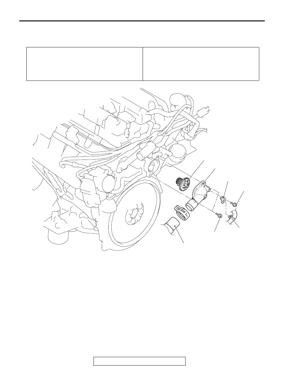
THERMOSTAT
REMOVAL AND INSTALLATION
M1141002402772
Pre-removal operation
• Engine Coolant Draining (Refer to
• Engine Upper Cover Removal (Refer to GROUP 16, Igni-
tion System − Ignition Coil
).
• Air Cleaner Intake Hose Removal (Refer to GROUP 15,
Air Cleaner
Post-installation operation
• Air Cleaner Intake Hose Installation (Refer to GROUP 15,
Air Cleaner
• Engine Upper Cover Installation (Refer to GROUP 16,
Ignition System − Ignition Coil
• Engine Coolant Refilling (Refer to
AC705834
24 ± 3 N·m
18 ± 2 ft-lb
10 ± 2 N·m
89 ± 17 in-lb
1
2
3
4
5
AC
Removal steps
<<A>>
>>B<<
1.
Radiator lower hose connection
2.
Control wiring harness clamp
connection
3.
Harness bracket
4.
Cooling water inlet hose fitting
>>A<<
5.
Thermostat
Removal steps (Continued)