Mitsubishi Lancer Evolution X. Manual - part 453


  Index      Mitsubishi     Mitsubishi Lancer Evolution X GS41EVO - service repair manual 2008 year


Search            


Content   ..  451  452  453  454   ..


Mitsubishi Lancer Evolution X. Manual - part 453


ON-VEHICLE SERVICE

TSB Revision

MULTIPORT FUEL INJECTION (MFI)

13A-877

7. While repeatedly revving the engine, measure the heated 

oxygen sensor output voltage.

Standard value:

CAUTION

• Be very careful when connecting the jumper wire; 

incorrect connection can damage the oxygen sensor.

• Be careful the heater is broken when voltage of beyond 

8V is applied to the oxygen sensor heater.

NOTE: If the temperature of sensing area does not reach 
the high temperature [of approximately 400

°

C (752

°

F) or 

more] even though the oxygen sensor is normal, the output 
voltage would be possibly low in spite of the rich air-fuel 
ratio. Therefore, if the output voltage is low, use a jumper 
wire to connect terminal No. 1 and terminal No. 2 of the oxy-
gen sensor with a (+) terminal and (

) terminal of 8 V power 

supply respectively, then check again.

8. If the output voltage is not within the standard value, replace 

the heated oxygen sensor.
NOTE: For removal and installation of the heated oxygen 
sensor, refer to GROUP 15, Exhaust Pipe and Main Muffler 


Removal and installation 

P.15-26

.

.

Heated oxygen sensor (rear)

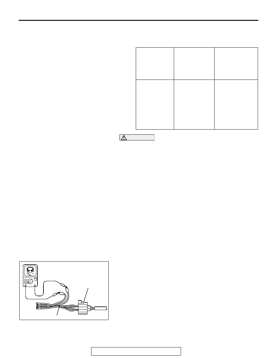
1. Disconnect the heated oxygen sensor connector and 

connect special tool MB991658 to the connector on the 
heated oxygen sensor side.

2. Measure the resistance between terminal No. 1 and terminal 

No. 2 on the heated oxygen sensor connector.

Standard value: 4.5  8.0 Ω [at 20 ° C (68 ° F)]

3. If the resistance deviates from standard value, replace the 

heated oxygen sensor.

4. Warm up the engine until engine coolant is 80° C (176° F) or 

higher.

5. Drive at 50 km/h (31 mph) or more for 10 minutes.

ENGINE

HEATED 
OXYGEN 
SENSOR 
OUTPUT 
VOLTAGE

REMARKS

When revving 
engine

0.6 − 1.0 V

If you make the 
air/fuel ratio rich 
by revving the 
engine repeatedly, 
a normal heated 
oxygen sensor will 
output a voltage of 
0.6 − 1.0 V.

AK604492AB

MB991658

Heated oxygen
sensor component
side connector

ON-VEHICLE SERVICE

TSB Revision

MULTIPORT FUEL INJECTION (MFI)

13A-878

6. Connect a digital voltage meter between terminal No. 3 and 

terminal No. 4.

7. Measure the output voltage of the heated oxygen sensor 

under the following driving.

• Transaxle: 2nd
• Drive with wide open throttle
• Engine: 3,500 r/min or more

Standard value:

NOTE: If the temperature of sensing area does not reach 
the high temperature [of approximately 400

°

C (752

°

F) or 

more] even though the oxygen sensor is normal, the output 
voltage would be possibly low in spite of the rich air-fuel 
ratio. 
NOTE: When the vehicle is driven with high loads, the tem-
perature of the sensing area of the oxygen sensor is suffi-
ciently high. Thus, it is not necessary to apply the voltage to 
the heater.

8. If the output voltage is not within the standard value, replace 

the heated oxygen sensor.
NOTE: For removal and installation of the heated oxygen 
sensor, refer to GROUP 15, Exhaust Pipe and Main Muffler 


Removal and installation 

P.15-26

.

INJECTOR CHECK

M1131005202022

.

<Checking the Operation Sound>

Using a stethoscope or long blade screwdriver, check the oper-
ation sound ("tick-tick-tick") of injectors during idling or during 
cranking. Check that as the engine speed increases, the fre-
quency of the operating sound also increases.
1. If the injector you are checking is not operating, you may 

hear the operating sound of the other injectors.

2. If no operating sound is heard from the injector that is being 

checked, check the injector drive circuit. If there is nothing 
wrong with the circuit, a defective injector or engine control 
module (ECM) is suspected.

.

HEATED OXYGEN 
SENSOR OUTPUT 
VOLTAGE

REMARKS

0.6 − 1.0 V

High load operation makes 
air/fuel ratio richer and 
normal heated oxygen 
sensor also can output 
voltage of 0.6 − 1.0 V.

AK604493AB

MB991658

Heated oxygen
sensor component
side connector

AK704440AB

Stethoscope

ON-VEHICLE SERVICE

TSB Revision

MULTIPORT FUEL INJECTION (MFI)

13A-879

<Checking the Coil Resistance>

1. Disconnect the injector connector.
2. Measure the resistance between terminal No. 1 and terminal 

No. 2.

Standard value: 10.5  13.5 Ω [at 20° C (68° F)]

3. If not within specification, replace the injector.
4. Connect the injector connector.

THROTTLE ACTUATOR CONTROL MOTOR 
CHECK

M1131051000876

.

<Operation Inspection>

WARNING

When checking the throttle valve operation, never 
insert fingers into the throttle valve. The extremely 
strong power of the throttle valve motor might trap 
and injure fingers.

1. Remove the air intake hose from the throttle body.
2. Set the ignition switch to the "ON" position.
3. Operate the accelerator pedal and confirm that the throttle 

valve is opening and closing accordingly.

.

<Checking the Terminal Resistance>

WARNING

If the throttle valve is operated in service, a finger 
might be injured as the result of being caught by the 
throttle valve. Make sure that the ignition switch is 
surely in "LOCK" (OFF) position before the service in 
order that the throttle valve cannot be operated.

1. Disconnect the electronic-controlled throttle valve connector.
2. Measure the resistance between terminal No. 1 and terminal 

No. 2.

Standard value: 0.3  80 Ω [at 20° C (68° F)]

NOTE: If the measured resistance deviates from the stan-
dard value, fully open the throttle valve with your finger more 
than five times, then check the result again. If the throttle 
valve control serve is not used for an extended period of 
time, the resistance may be increased as a result of internal 
forming of oxide film. Therefore, it means that the oxide film 
can be removed through a self cleaning capability of the 
throttle valve control servo, if forcibly moved.

3. If the resistance is outside the standard value, replace the 

throttle body assembly.

AK604494

1 2

AB

Injector
connector

6

1 2 3 4 5

AK604495AC

Electronic-controlIed
throttle valve connector

ON-VEHICLE SERVICE

TSB Revision

MULTIPORT FUEL INJECTION (MFI)

13A-880

ENGINE OIL CONTROL VALVE CHECK

M1131053200638

Required Special Tools:

• MB991658: Test Harness

Intake engine oil control valve

.

<Checking the Operation Sound>

1. Disconnect the intake engine oil control valve connector.

CAUTION

To prevent the coil from burning, keep the duration of the 
voltage application as short as possible.
2. Check that the operation sound of the intake engine oil 

control valve can be heard when the positive battery voltage 
is supplied to the intake engine oil control valve. (Use the 
special tool MB991658 to connect terminal No. 2 of the 
intake engine oil control valve connector to the positive 
battery terminal and terminal No. 1 to the negative battery 
terminal.)

3. If the operation sound cannot be heard, replace the intake 

engine oil control valve.

.

<Checking the Coil Resistance>

1. Disconnect the intake engine oil control valve connector.
2. Measure resistance between terminal No. 1 and terminal 

No. 2 of the connector at the intake engine oil control valve 
side.

Standard value: 6.9  7.9 Ω [at 20° C (68° F)]

3. If resistance is not within the standard value, replace the 

intake engine oil control valve.

Exhaust engine oil control valve

.

<Checking the Operation Sound>

1. Disconnect the exhaust engine oil control valve connector.

AK703721AB

Intake engine oil
control valve

MB991658

AK704082

1 2

AB

Intake engine oil
control valve connector


Content   ..  451  452  453  454   ..