Mitsubishi Lancer Evolution X. Manual - part 438


  Index      Mitsubishi     Mitsubishi Lancer Evolution X GS41EVO - service repair manual 2008 year


Search            


Content   ..  436  437  438  439   ..


Mitsubishi Lancer Evolution X. Manual - part 438


MULTIPORT FUEL INJECTION (MFI) DIAGNOSIS

TSB Revision

MULTIPORT FUEL INJECTION (MFI)

13A-817

DIAGNOSIS

Required Special Tools:

• MB991958: Scan Tool (M.U.T.-III Sub Assembly)

• MB991824: V.C.I.
• MB991827: USB Cable
• MB991910: Main Harness A

STEP 1. Check harness connector B-15 at engine oil 
pressure switch for damage.
Q: Is the harness connector in good condition?

YES : Go to Step 2.
NO :  Repair or replace it. Refer to GROUP 00E, Harness 

Connector Inspection 

P.00E-2

. Then go to Step 5 .

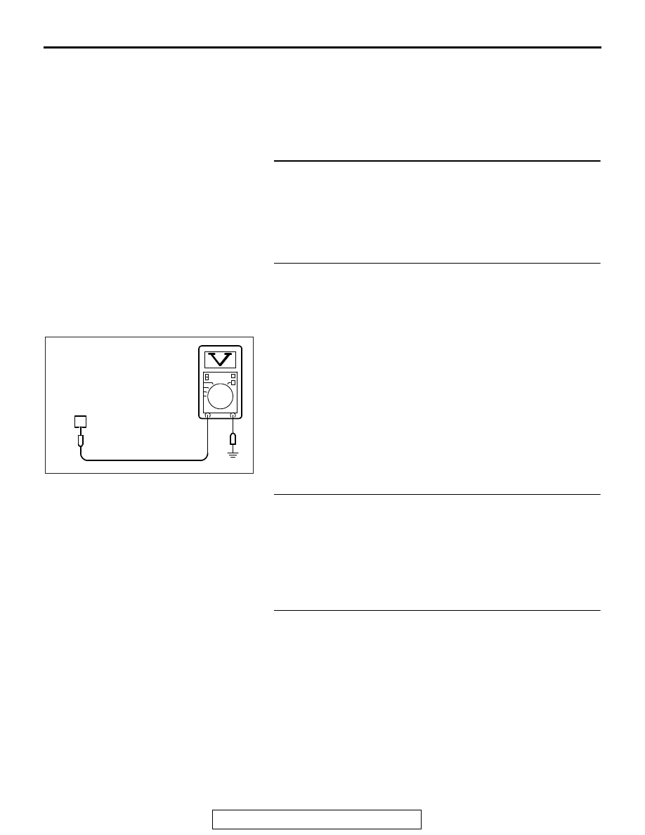
STEP 2. Measure the power supply voltage at engine oil 
pressure switch connector B-15.
(1) Disconnect the connector B-15 measure at the harness 

side.

(2) Turn the ignition switch to the "ON" position.
(3) Measure the voltage between terminal No. 1 and ground.

• The voltage should equal battery positive voltage.

(4) Turn the ignition switch to the "LOCK" (OFF) position.
Q: Is battery positive voltage (approximately 12 volts) 

present?
YES : 
Go to Step 5.
NO :  Go to Step 3.

STEP 3. Check harness connector B-09 ECM connector for 
damage.
Q: Is the connector in good condition?

YES : Go to Step 4.
NO :  Repair or replace it. Refer to GROUP 00E, Harness 

Connector Inspection 

P.00E-2

. Then confirm that the 

malfunction symptom is eliminated.

STEP 4. Check for open circuit and short circuit to ground 
between ECM connector B-09 (terminal No. 36) and engine 
oil pressure switch connector B-15 (terminal No. 1)
Q: Is the harness wire in good condition?

YES : Replace the ECM. When the ECM is replaced, 

register the ID code. Refer to GROUP 42B, Diagnosis 
− ID Code Registration Judgment Table <Vehicles with 

KOS> 

P.42B-14

 or GROUP 42C, Diagnosis − ID 

Codes Registration Judgment Table <Vehicles with 
WCM> 

P.42C-10

. Then confirm that the malfunction 

symptom is eliminated.

NO :  Repair it. Then confirm that the malfunction symptom 

is eliminated.

1

AK700522AC

B-15 harness
connector:
component side

MULTIPORT FUEL INJECTION (MFI) DIAGNOSIS

TSB Revision

MULTIPORT FUEL INJECTION (MFI)

13A-818

STEP 5. Check harness connector B-09 ECM connector for 
damage.
Q: Is the connector in good condition?

YES : Go to Step 6.
NO :  Repair or replace it. Refer to GROUP 00E, Harness 

Connector Inspection 

P.00E-2

. Then confirm that the 

malfunction symptom is eliminated.

STEP 6. Check for harness damage between ECM 
connector B-09 (terminal No. 36) and engine oil pressure 
switch connector B-15 (terminal No. 1)
Q: Is the harness wire in good condition?

YES : Replace the engine oil pressure switch. Then confirm 

that the malfunction symptom is eliminated.

NO :  Repair it. Then confirm that the malfunction symptom 

is eliminated.

DATA LIST REFERENCE TABLE

M1131152004384

CAUTION

• When shifting the shift lever to D range, the brakes should be applied so that the vehicle does not 

move forward.

• Driving tests always need two persons: one driver and one observer.

NOTE: *

1

: In a new vehicle [driven approximately 500 km (311 mile) or less], the mass airflow sensor output 

value is sometimes 10 % higher than the standard value.
NOTE: *

2

: The injector drive time represents the time when the cranking speed is at 250 r/min or below when 

the power supply voltage is 11 volts.
NOTE: *

3

: In a new vehicle [driven approximately 500 km (311 mile) or less], the injector drive time is some-

times 10 % longer than the standard time.
NOTE: *

4

: Vehicles for Canada, the headlight, taillight, etc. remain lit even when the lighting switch is in "OFF" 

position but this is no problem for checks.
NOTE: *

5

: Data items are displayed on M.U.T.-III display, but the in-line 4 engine is not applicable and its data 

is displayed as "N/A".

M.U.T.-III 
SCAN 
TOOL 
DISPLAY

ITEM 
NO. 

INSPECTION 
ITEM

INSPECTION REQUIREMENT

NORMAL 
CONDITION

INSPECTION 
PROCEDURE 
NO.

REFERENCE 
PAGE

A/C 
compress
or relay

93

A/C 
compressor 
clutch relay

• Engine: warming up, idling
• A/C switch: "OFF"

OFF

Procedure 
No. 27

P.13A-813

• Engine: 

warming 
up, idling

• A/C switch: 

"ON"

A/C 
compressor 
clutch is not 
operating

OFF

A/C 
compressor 
clutch is 
operating

ON

MULTIPORT FUEL INJECTION (MFI) DIAGNOSIS

TSB Revision

MULTIPORT FUEL INJECTION (MFI)

13A-819

A/C SW

76

A/C switch

• Engine: warming up, idling
• A/C switch: "OFF"

OFF

Procedure 
No. 27

P.13A-813

• Engine: 

warming 
up, idling

• A/C switch: 

"ON"

A/C 
compressor 
clutch is not 
operating

OFF

A/C 
compressor 
clutch is 
operating

ON

Absolute 
load 
value

72

Absolute load 
value

Engine: 
warming up

Engine is 
idling

16 − 28 %

2,500 r/min

12 − 23 %

Revving 
engine

Load value 
increases 
according to 
amount of 
revving.

Airflow 
sensor

10

Mass airflow 
sensor*

1

• Engine 

coolant 
temperatur
e: 80 − 

95° C (176 − 

203° F)

• Lights, 

electric 
cooling fan 
and all 
accessories
: "OFF"*

4

• Transaxle: 

Neutral 
(TC-SST: 
"P" range)

Engine is 
idling

1,300 − 1,650 

mV

2,500 r/min

1,620 − 2,100 

mV

Engine is 
revved 

Increases in 
response to 
revving

M.U.T.-III 
SCAN 
TOOL 
DISPLAY

ITEM 
NO. 

INSPECTION 
ITEM

INSPECTION REQUIREMENT

NORMAL 
CONDITION

INSPECTION 
PROCEDURE 
NO.

REFERENCE 
PAGE

MULTIPORT FUEL INJECTION (MFI) DIAGNOSIS

TSB Revision

MULTIPORT FUEL INJECTION (MFI)

13A-820

Airflow 
sensor

AA

Mass airflow 
sensor*

1

• Engine 

coolant 
temperatur
e: 80 − 

95° C (176 − 

203° F)

• Lights, 

electric 
cooling fan 
and all 
accessories
: "OFF"*

4

• Transaxle: 

Neutral 
(TC-SST: 
"P" range)

Engine is 
idling

1.8 − 4.4 g/s

2,500 r/min

8.0 − 12.0 g/s

Engine is 
revved

Increases in 
response to 
revving

APP 
sensor 
(main)

11

Accelerator 
pedal position 
sensor (main)

Ignition switch: 
"ON"

Release the 
accelerator 
pedal

900 − 1,100 

mV

Code No. 
P2122, 
P2123

P.13A-638

P.13A-643

Depress the 
accelerator 
pedal 
gradually

Increases in 
response to 
the pedal 
depression 
stroke

Depress the 
accelerator 
pedal fully

4,000 mV or 
more

APP 
sensor 
(main)

BE

Accelerator 
pedal position 
sensor (main)

Ignition switch: 
"ON"

Release the 
accelerator 
pedal

18 − 22 %

Code No. 
P2122, 
P2123

P.13A-638

P.13A-643

Depress the 
accelerator 
pedal 
gradually

Increases in 
response to 
the pedal 
depression 
stroke

Depress the 
accelerator 
pedal fully

80 % or more

M.U.T.-III 
SCAN 
TOOL 
DISPLAY

ITEM 
NO. 

INSPECTION 
ITEM

INSPECTION REQUIREMENT

NORMAL 
CONDITION

INSPECTION 
PROCEDURE 
NO.

REFERENCE 
PAGE


Content   ..  436  437  438  439   ..