Mitsubishi Lancer Evolution X. Manual - part 421


  Index      Mitsubishi     Mitsubishi Lancer Evolution X GS41EVO - service repair manual 2008 year


Search            


Content   ..  419  420  421  422   ..


Mitsubishi Lancer Evolution X. Manual - part 421


MULTIPORT FUEL INJECTION (MFI) DIAGNOSIS

TSB Revision

MULTIPORT FUEL INJECTION (MFI)

13A-749

Inspection procedure 17: Too high CO and HC concentration when idling

.

COMMENT

• Abnormal air/fuel ratio is suspected.

.

TROUBLESHOOTING HINTS (The most 
likely causes for this case:)

• Malfunction of the fuel pump system.

• Malfunction of the heated oxygen sensor.
• Malfunction of the ignition system.
• Poor compression.
• Improper operation of the PCV valve.
• Malfunction of the evaporative emission control 

system.

• Malfunction of the ECM.

DIAGNOSIS

Required Special Tools:

• MB991958: Scan Tool (M.U.T.-III Sub Assembly)

• MB991824: V.C.I.
• MB991827: USB Cable
• MB991910: Main Harness A

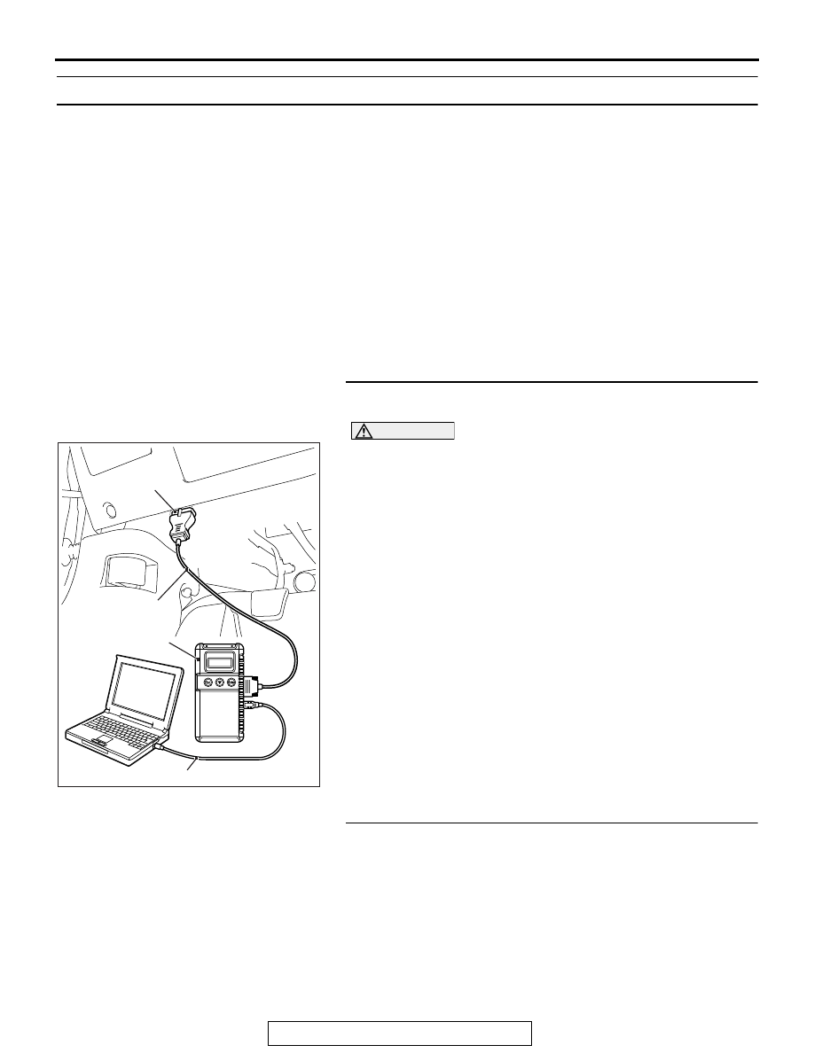
STEP 1. Using scan tool MB991958, read the diagnostic 
trouble code (DTC).

CAUTION

To prevent damage to scan tool MB991958, always turn the 
ignition switch to the "LOCK" (OFF) position before con-
necting or disconnecting scan tool MB991958.
(1) Connect scan tool MB991958 to the data link connector.
(2) Turn the ignition switch to the "ON" position.
(3) Read the DTC.
(4) Turn the ignition switch to the "LOCK" (OFF) position.
Q: Is any DTC set?

YES : Refer to Diagnostic Trouble Code Chart 

P.13A-48

.

NO :  Go to Step 2.

STEP 2. Check the ignition timing.
Refer to GROUP 11A, On-vehicle Service − Ignition Timing 

Check 

P.11A-10

.

Q: Is the ignition timing normal?

YES : Go to Step 3.
NO :  Check for installed conditions of the timing chain. 

Then confirm that the malfunction symptom is 
eliminated.

AC608435

Data link connector

MB991827

MB991824

MB991910

AB

MULTIPORT FUEL INJECTION (MFI) DIAGNOSIS

TSB Revision

MULTIPORT FUEL INJECTION (MFI)

13A-750

STEP 3. Using scan tool MB991958, check data list.
(1) Turn the ignition switch to the "ON" position.
(2) Check the following items in the data list. Refer to Data List 

Reference Table 

P.13A-818

.

a. Item 5: Intake Air Temperature Sensor.
b. Item 6: Engine Coolant Temperature Sensor.

c. Item AC: Heated Oxygen Sensor (front).

d. Item AD: Heated Oxygen Sensor (rear).

(3) Turn the ignition switch to the "LOCK" (OFF) position.
Q: Are they operating properly?

YES : Go to Step 4.
NO :  Repair or replace it. Then confirm that the malfunction 

symptom is eliminated.

STEP 4. Check the fuel pressure.
Refer to Fuel Pressure Test 

P.13A-865

.

Q: Is the fuel pressure normal?

YES : Go to Step 5.
NO :  Repair or replace it. Then confirm that the malfunction 

symptom is eliminated.

STEP 5. Check the spark plugs.
Refer to GROUP 16, Ignition System − On-vehicle Service − 

Spark Plug Check And Cleaning 

P.16-39

.

Q: Are there any abnormalities?

YES : Replace the spark plug. Then confirm that the 

malfunction symptom is eliminated.

NO :  Go to Step 6.

STEP 6. Check the ignition coil.
Refer to GROUP 16, Ignition System − On-vehicle Service − 

Ignition Coil Check 

P.16-37

.

Q: Are there any abnormalities?

YES : Replace the ignition coil. Then confirm that the 

malfunction symptom is eliminated.

NO :  Go to Step 7.

STEP 7. Check the compression pressure.
Refer to GROUP 11A, On-vehicle Service − Compression Pres-

sure Check 

P.11A-15

.

Q: Is the compression pressure normal?

YES : Go to Step 8.
NO :  Repair it. Then confirm that the malfunction symptom 

is eliminated.

MULTIPORT FUEL INJECTION (MFI) DIAGNOSIS

TSB Revision

MULTIPORT FUEL INJECTION (MFI)

13A-751

STEP 8. Check the positive crankcase ventilation system.
Refer to GROUP 17, Emission Control − Positive Crankcase 

Ventilation System − Positive Crankcase Ventilation System 

Check 

P.17-72

.

Q: Is the positive crankcase ventilation system?

YES : Go to Step 9.
NO :  Repair it. Then confirm that the malfunction symptom 

is eliminated.

STEP 9. Check the evaporative emission control system.
Refer to GROUP 17, Emission Control − Evaporative Emission 

Control System − Purge Control System Check (Purge Flow 

Check) 

P.17-75

.

Q: Is the purge control system normal?

YES : Check the following items, and repair or replace the 

defective items.

a. Check if the injectors are clogged.

Then confirm that the malfunction symptom is 

eliminated.

NO :  Repair it. Then confirm that the malfunction symptom 

is eliminated.

Inspection procedure 18: Transient, mass emission tailpipe test failure

.

COMMENT

• The test is failed when the air/fuel ratio is not con-

trolled to the ideal air/fuel ratio. This occurs due 
to the feedback control by heated oxygen sensor 
signals, or deteriorated catalyst.

NOTE: If the three-way catalyst temperature is low 
when checking the exhaust gas, the three-way cata-
lyst cannot sufficiently clean the emissions. Warm up 
the engine sufficiently before checking the exhaust, 
and check immediately.

.

TROUBLESHOOTING HINTS (The most 
likely causes for this case:)

• Malfunction of air/fuel ratio control system.
• Malfunction of the fuel pump system.
• Malfunction of the ignition system.
• Poor compression.
• Improper operation of the PCV valve
• Malfunction of the evaporative emission control 

system

• Deteriorated catalyst.

DIAGNOSIS

Required Special Tools:

• MB991958: Scan Tool (M.U.T.-III Sub Assembly)

• MB991824: V.C.I.
• MB991827: USB Cable
• MB991910: Main Harness A

STEP 1. Check the exhaust gas with the engine at normal 
operating temperature.
Q: Was the exhaust gas checked with engine warmed 

sufficiently?
YES : 
Go to Step 2.
NO :  Check it again after enough warm up.

MULTIPORT FUEL INJECTION (MFI) DIAGNOSIS

TSB Revision

MULTIPORT FUEL INJECTION (MFI)

13A-752

STEP 2. Check the following items.
(1) Check the following items.

a. Check all vacuum hoses and connectors.
b. Check electrical wires and connectors for obvious prob-

lems.

Q: Are they normal?

YES : Go to Step 3.
NO :  Repair or replace it. Then confirm that the malfunction 

symptom is eliminated.

STEP 3. Check the driveability.
Q: Is the driveability normal?

YES : Go to Step 4.
NO :  Refer to Trouble Symptom Chart 

P.13A-52

.

STEP 4. Using scan tool MB991958, read the diagnostic 
trouble code (DTC).

CAUTION

To prevent damage to scan tool MB991958, always turn the 
ignition switch to the "LOCK" (OFF) position before con-
necting or disconnecting scan tool MB991958.
(1) Connect scan tool MB991958 to the data link connector.
(2) Turn the ignition switch to the "ON" position.
(3) Read the DTC.
(4) Turn the ignition switch to the "LOCK" (OFF) position.
Q: Is any DTC set?

YES : Refer to Diagnostic Trouble Code Chart 

P.13A-48

.

NO :  Go to Step 5.

STEP 5. Check the ignition timing.
Refer to GROUP 11A, On-vehicle Service − Ignition Timing 

Check 

P.11A-10

.

Q: Is the ignition timing normal?

YES : Go to Step 6.
NO :  Check that the crankshaft position sensor and timing 

chain case are in the correct position. Then confirm 
that the malfunction symptom is eliminated.

AC608435

Data link connector

MB991827

MB991824

MB991910

AB


Content   ..  419  420  421  422   ..