Mitsubishi Lancer Evolution X. Manual - part 404


  Index      Mitsubishi     Mitsubishi Lancer Evolution X GS41EVO - service repair manual 2008 year


Search            


Content   ..  402  403  404  405   ..


Mitsubishi Lancer Evolution X. Manual - part 404


MULTIPORT FUEL INJECTION (MFI) DIAGNOSIS

TSB Revision

MULTIPORT FUEL INJECTION (MFI)

13A-681

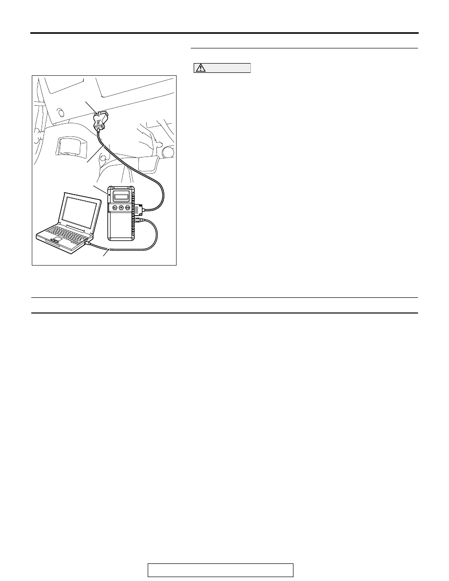
STEP 1. Test the OBD-II drive cycle.

CAUTION

To prevent damage to scan tool MB991958, always turn the 
ignition switch to the "LOCK" (OFF) position before con-
necting or disconnecting scan tool MB991958.
(1) Connect scan tool MB991958 to the data link connector.
(2) Turn the ignition switch to the "ON" position.
(3) Carry out the test drive with the drive cycle pattern. Refer to 

Diagnostic Function OBD-II Drive Cycle − Pattern 23 

P.13A-9

.

(4) Check the diagnostic trouble code (DTC).
Q: Is DTC P2253 set?

YES : Replace the ECM. When the ECM is replaced, 

register the ID code. Refer to GROUP 42B, ID Code 
Registration Necessity Judgment Table <Vehicles 
with KOS> 

P.42B-11

 or GROUP 42C, ID Codes 

Registration Judgment Table <Vehicles with WCM> 

P.42C-9

NO :  It can be assumed that this malfunction is intermittent. 

Refer to GROUP 00, How to Use 
Troubleshooting/Inspection Service Points − How to 

Cope with Intermittent Malfunctions 

P.00-15

.

DTC P2263: Intake Charge System Malfunction

.

TECHNICAL DESCRIPTION

• The ECM indicates or monitors a minimum pre-

scribed value of volumetric efficiency within the 
boost operation range, which is determined by 
the signals from the throttle position sensor and 
the engine speed.

.

DTC SET CONDITIONS

Check Conditions

• Engine speed is between 3,000 and 5,000 r/min.
• Throttle position sensor (main) output voltage is 

higher than 2 volts.

Judgment Criterion

• Volumetric efficiency is lower than 100 percent for 

2 seconds.

.

FAIL-SAFE AND BACKUP FUNCTION

• Fuel is cut in engine overboost condition.

.

TROUBLESHOOTING HINTS (The most 
likely causes for this code to be set are:)

• Turbocharger wastegate actuator failed.
• Turbocharger wastegate regulating valve failed.
• Charging pressure control system failed.
• Intake charge pressure leak.
• ECM failed.

DIAGNOSIS

Required Special Tools:

• MB991958: Scan Tool (M.U.T.-III Sub Assembly)

• MB991824: V.C.I.
• MB991827: USB Cable
• MB991910: Main Harness A

AC608435

Data link connector

MB991827

MB991824

MB991910

AB

MULTIPORT FUEL INJECTION (MFI) DIAGNOSIS

TSB Revision

MULTIPORT FUEL INJECTION (MFI)

13A-682

STEP 1. Using scan tool MB991958, check actuator test 
item 20: Turbocharger Wastegate Solenoid.

CAUTION

To prevent damage to scan tool MB991958, always turn the 
ignition switch to the "LOCK" (OFF) position before con-
necting or disconnecting scan tool MB991958.
(1) Connect scan tool MB991958 to the data link connector.
(2) Turn the ignition switch to the "ON" position.
(3) Set scan tool MB991958 to the actuator test mode for item 

20, turbocharger wastegate solenoid.

• An operation sound should be heard and vibration 

should be felt when the turbocharger wastegate sole-
noid is operated.

(4) Turn the ignition switch to the "LOCK" (OFF) position.
Q: Is the solenoid operating properly?

YES : Go to Step 2.
NO :  Refer to DTC P0243 − Turbocharger Wastegate 

Solenoid 1 Circuit 

P.13A-352

, DTC P0247 − 

Turbocharger Wastegate Solenoid 2 Circuit 

P.13A-359

.

STEP 2. Check the intake charge pressure.
Refer to GROUP 15, On-vehicle Service − Intake Charge Pres-

sure Check. 

P.15-5

Q: Are there any abnormalities?

YES : Repair or replace it. Then go to Step 5.
NO :  Go to Step 3.

STEP 3. Check the intake charge pressure control system.
Refer to GROUP 15, On-vehicle Service − Intake Charge Pres-

sure Control System Check. 

P.15-7

Q: Are there any abnormalities?

YES : Repair or replace it. Then go to Step 5.
NO :  Go to Step 4.

AC608435

Data link connector

MB991827

MB991824

MB991910

AB

MULTIPORT FUEL INJECTION (MFI) DIAGNOSIS

TSB Revision

MULTIPORT FUEL INJECTION (MFI)

13A-683

STEP 4. Using scan tool MB991958, read the diagnostic 
trouble code (DTC).
(1) Turn the ignition switch to the "ON" position.
(2) Set scan tool MB991958 to the data reading mode for item 

13, Throttle Position Sensor (main).

CAUTION

During a test drive, the data list must be read by someone 
other than the driver.
(3) Accelerate the vehicle within the engine speed range of 

3,000 to 5,000 r/min while a minimum of 2 volts is being 
output by the throttle position sensor (main).

(4) After completing the test drive, read the DTC. Turn the 

ignition switch to the "LOCK" (OFF) position.

Q: Is the DTC P2263 set?

YES : Replace the ECM. When the ECM is replaced, 

register the ID code. Refer to GROUP 42B, ID code 
Registration Necessity Judgment Table <Vehicles 
with KOS> 

P.42B-11

 or GROUP 42C, ID code 

Registration Judgment Table <Vehicles with WCM> 

P.42C-9

. Then go to Step 5.

NO :  It can be assumed that this malfunction is 

intermittent.Refer to GROUP 00, How to Use 
Troubleshooting/ Inspection Service Points − How to 

Cope with Intermittent Malfunctions 

P.00-15

.

STEP 5. Using scan tool MB991958, read the diagnostic 
trouble code (DTC).
(1) Turn the ignition switch to the "ON" position.
(2) Set scan tool MB991958 to the data reading mode for item 

13, Throttle Position Sensor (main).

CAUTION

During a test drive, the data list must be read by someone 
other than the driver.
(3) Accelerate the vehicle within the engine speed range of 

3,000 to 5,000 r/min while a minimum of 2 volts is being 
output by the throttle position sensor (main).

(4) After completing the test drive, read the DTC. Turn the 

ignition switch to the "LOCK" (OFF) position.

Q: Is the DTC P2263 set?

YES : Retry the troubleshooting.
NO :  The inspection is complete.

MULTIPORT FUEL INJECTION (MFI) DIAGNOSIS

TSB Revision

MULTIPORT FUEL INJECTION (MFI)

13A-684

DTC U0001: Bus Off

CAUTION

• If the ECM output the DTC U0001, make sure 

to diagnose the CAN bus line.

• Before replacing the ECU, make sure that the 

communication circuit is operating normally.

.

DTC SET CONDITIONS

Check Conditions

• Always

Judgement Criteria

• Bus off error detected

.

FAIL-SAFE AND BACKUP FUNCTION

• None

.

TROUBLESHOOTING HINTS (The most 
likely causes for this code to be set are:)

• CAN line harness damage or connector damage.
• ECM failed. 

DIAGNOSIS

Required Special Tools:

• MB991958: Scan tool (M.U.T.-III Sub Assembly)

• MB991824: V.C.I.
• MB991827: USB Cable
• MB991910: Main Harness A

STEP 1. Using scan tool MB991958, diagnose CAN bus 
line.

CAUTION

To prevent damage to scan tool MB991958, always turn the 
ignition switch to the "LOCK" (OFF) position before con-
necting or disconnecting san tool MB991958.
(1) Connect scan tool MB991958 to the data link connector.
(2) Turn the ignition switch to the "ON" position.
(3) Diagnose CAN bus line.
(4) Turn the ignition switch the "LOCK" (OFF) position.
Q: Is the CAN bus line normal?

YES : Go to Step 2.
NO :  Repair the CAN bus line. Refer to GROUP 54C, Can 

bus Diagnostics Table 

P.54C-15

. Then go to Step 3.

AC608435

Data link connector

MB991827

MB991824

MB991910

AB


Content   ..  402  403  404  405   ..