Mitsubishi Lancer Evolution X. Manual - part 366


  Index      Mitsubishi     Mitsubishi Lancer Evolution X GS41EVO - service repair manual 2008 year


Search            


Content   ..  364  365  366  367   ..


Mitsubishi Lancer Evolution X. Manual - part 366


MULTIPORT FUEL INJECTION (MFI) DIAGNOSIS

TSB Revision

MULTIPORT FUEL INJECTION (MFI)

13A-529

.

Check Conditions 

• Engine coolant temperature is higher than 65° C 

(149° F). 

• Drive for 4 seconds or more with the vehicle 

speed is 50 km/h (31 mph) or more. Stop the 
vehicle [vehicle speed is 1.5 km/h (1.0 mph) or 
less]. Repeat 10 times or more. 

Judgement Criterion 

• Power steering pressure switch continues to be 

"ON". 

.

FAIL-SAFE AND BACKUP FUNCTION

• None

.

OBD-II DRIVE CYCLE PATTERN

None.

.

 TROUBLESHOOTING HINTS (The most 
likely causes for this code to be set are:) 

• Power steering pressure switch failed. 
• Open or shorted power steering pressure switch 

circuit, harness damage, or connector damage. 

• ECM failed. 

DIAGNOSIS 

Required Special Tools:

• MB991958: Scan tool (M.U.T.-III Sub Assembly)

• MB991824: V.C.I.
• MB991827: USB Cable
• MB991910: Main Harness A

• MB992110: Power Plant ECU Check Harness

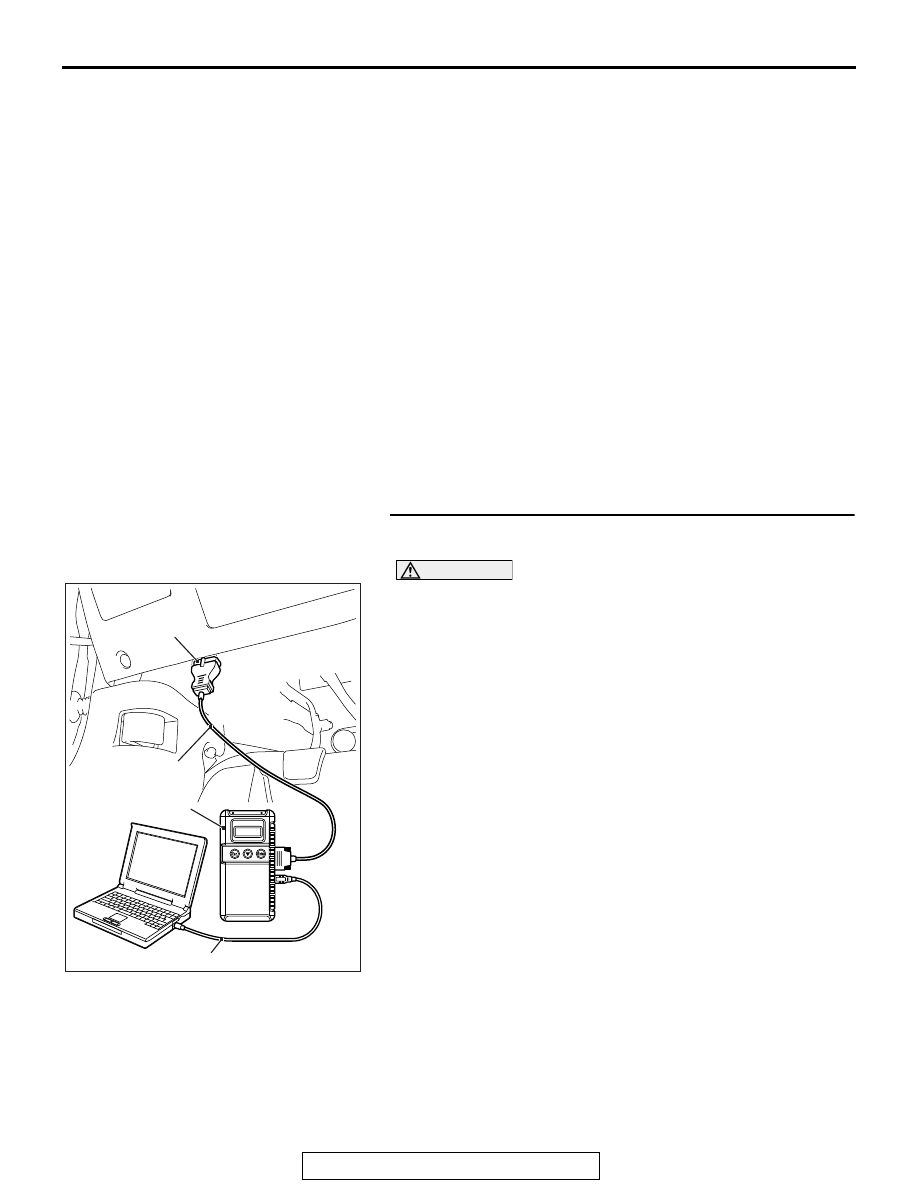
STEP 1. Using scan tool MB991958, check data list item 83: 
Power Steering Pressure Switch. 

CAUTION

To prevent damage to scan tool MB991958, always turn the 
ignition switch to the "LOCK" (OFF) position before con-
necting or disconnecting scan tool MB991958. 
(1) Connect scan tool MB991958 to the data link connector. 
(2) Start the engine and run at idle. 
(3) Set scan tool MB991958 to the data reading mode for item 

83, Power Steering Pressure Switch. 

• If the steering wheel is not turned while idling, "OFF" will 

be displayed.

• If the steering wheel is turned while idling, "ON" will be 

displayed.

(4) Turn the ignition switch to the "LOCK" (OFF) position. 
Q: Is the switch operating properly?

YES :  It can be assumed that this malfunction is 

intermittent. Refer to GROUP 00, How to Use 
Troubleshooting/Inspection Service Points − How to 

Cope with Intermittent Malfunctions 

P.00-15

.

NO :  Go to Step 2.

AC608435

Data link connector

MB991827

MB991824

MB991910

AB

MULTIPORT FUEL INJECTION (MFI) DIAGNOSIS

TSB Revision

MULTIPORT FUEL INJECTION (MFI)

13A-530

STEP 2. Measure the power supply voltage at power 
steering pressure switch connector B-19 by backprobing. 
(1) Do not disconnect the connector B-19. 
(2) Start the engine and run at idle. 
(3) Measure the voltage between terminal No. 1 and ground by 

backprobing. 

• When steering wheel is not turned, voltage should be 

battery positive voltage. 

• When steering wheel is turned, voltage should be 1 volt 

or less. 

(4) Turn the ignition switch to the "LOCK" (OFF) position. 
Q: Is the measured voltage within the specified range? 

YES : Go to Step 3. 
NO :  Go to Step 5. 

STEP 3. Check harness connector B-19 at power steering 
pressure switch for damage. 
Q: Is the harness connector in good condition? 

YES : Go to Step 4. 
NO :  Repair or replace it. Refer to GROUP 00E, Harness 

Connector Inspection 

P.00E-2

. Then go to Step 13. 

STEP 4. Using scan tool MB991958, check data list item 83: 
Power Steering Pressure Switch. 
(1) Start the engine and run at idle. 
(2) Set scan tool MB991958 to the data reading mode for item 

83, Power Steering Pressure Switch. 

• If the steering wheel is not turned while idling, "OFF" will 

be displayed. 

• If the steering wheel is turned while idling, "ON" will be 

displayed. 

(3) Turn the ignition switch to the "LOCK" (OFF) position. 
Q: Is the switch operating properly? 

YES : It can be assumed that this malfunction is intermittent. 

Refer to GROUP 00, How to Use 
Troubleshooting/Inspection Service Points − How to 

Cope with Intermittent Malfunctions 

P.00-15

.

NO :  Replace the ECM. When the ECM is replaced, 

register the ID code. Refer to GROUP 42B, ID Code 
Registration Necessity Judgment Table <Vehicles 
with KOS> 

P.42B-11

 or GROUP 42C, ID Codes 

Registration Judgment Table <Vehicles with WCM> 

P.42C-9

. Then go to Step 13. 

STEP 5. Check harness connector B-19 at power steering 
pressure switch for damage. 
Q: Is the harness connector in good condition? 

YES : Go to Step 6. 
NO :  Repair or replace it. Refer to GROUP 00E, Harness 

Connector Inspection 

P.00E-2

. Then go to Step 13.

AK704285

1

B-19 harness 
connector: 
harness side

AB

MULTIPORT FUEL INJECTION (MFI) DIAGNOSIS

TSB Revision

MULTIPORT FUEL INJECTION (MFI)

13A-531

STEP 6. Measure the power supply voltage at power 
steering pressure switch harness side connector B-19. 
(1) Disconnect the connector B-19 and measure at the harness 

side. 

(2) Turn the ignition switch to the "ON" position. 
(3) Measure the voltage between terminal No. 1 and ground. 

• Voltage should be battery positive voltage. 

(4) Turn the ignition switch to the "LOCK" (OFF) position. 
Q: Is battery positive voltage (approximately 12 volts) 

present?
YES : 
Go to Step 10. 
NO :  Go to Step 7. 

STEP 7. Check harness connector B-09 at ECM for 
damage. 
Q: Is the harness connector in good condition? 

YES : Go to Step 8. 
NO :  Repair or replace it. Refer to GROUP 00E, Harness 

Connector Inspection 

P.00E-2

. Then go to Step 13.

AK704286

1

B-19 harness 
connector: 
component side

AB

MULTIPORT FUEL INJECTION (MFI) DIAGNOSIS

TSB Revision

MULTIPORT FUEL INJECTION (MFI)

13A-532

STEP 8. Measure the power supply voltage at ECM 
connector B-09 by using power plant ECU check harness 
special tool MB992110. 
(1) Disconnect all ECM connectors. Connect the power plant 

ECU check harness special tool MB992110 between the 
separated connectors. 

(2) Disconnect the power steering pressure switch connector 

B-19. 

(3) Turn the ignition switch to the "ON" position. 

(4) Measure the voltage between terminal No. 58 and ground. 

• Voltage should be between battery positive voltage. 

(5) Turn the ignition switch to the "LOCK" (OFF) position. 
Q: Is battery positive voltage (approximately 12 volts) 

present?
YES : 
Repair harness wire between power steering 

pressure switch connector B-19 (terminal No. 1) and 
ECM connector B-09 (terminal No. 58) because of 
open circuit. Then go to Step 13

NO :  Go to Step 9.

STEP 9. Check for short circuit to ground between power 
steering pressure switch connector B-19 (terminal No. 1) 
and ECM connector B-09 (terminal No. 58). 
Q: Is the harness wire in good condition? 

YES : Replace the ECM. When the ECM is replaced, 

register the ID code. Refer to GROUP 42B, ID Code 
Registration Necessity Judgment Table <Vehicles 
with KOS> 

P.42B-11

 or GROUP 42C, ID Codes 

Registration Judgment Table <Vehicles with WCM> 

P.42C-9

. Then go to Step 13.

NO :  Repair it. Then go to Step 13.

AK604040

ECM

AB

Body side harness 

MB992110

AK604213

16 15 14 13 12 11 10 9 8 7 6 5 4 3

2

1

32 31 30 29 28 27 26 25 24 23 22 21 20 19 18 17

48 47 46 45 44 43 42 41 40 39 38 37 36 35 34 33

64 63 62 61 60 59 58 57 56 55 54 53 52 51 50 49

AB

Power plant ECU
check harness connector


Content   ..  364  365  366  367   ..