Mitsubishi Lancer Evolution X. Manual - part 352


  Index      Mitsubishi     Mitsubishi Lancer Evolution X GS41EVO - service repair manual 2008 year


Search            


Content   ..  350  351  352  353   ..


Mitsubishi Lancer Evolution X. Manual - part 352


MULTIPORT FUEL INJECTION (MFI) DIAGNOSIS

TSB Revision

MULTIPORT FUEL INJECTION (MFI)

13A-473

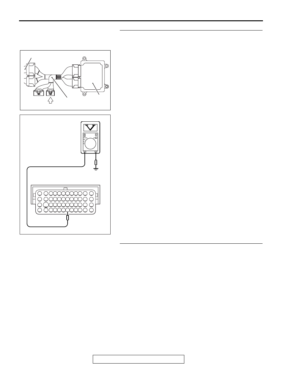
STEP 9. Measure the sensor output voltage at ECM 
connector B-10 by using power plant ECU check harness 
special tool MB992110.
(1) Disconnect all ECM connectors. Connect the power plant 

ECU check harness special tool MB992110 between the 
separated connectors.

(2) Turn the ignition switch to the "ON" position.
(3) Remove the fuel cap

(4) Measure the voltage between terminal No. 112 and ground.

• Voltage should be between 1.5 and 3.5 volts.

(5) Turn the ignition switch to the "LOCK" (OFF) position.
Q: Is the measured voltage normal?

YES : Go to Step 11 .
NO :  Go to Step 10 .

STEP 10. Check for open circuit and short circuit to 
ground between fuel tank differential pressure sensor 
connector D-21 (terminal No. 1) and ECM connector B-10 
(terminal No. 112).
NOTE: Check harness after checking intermediate connector 
C-47. If intermediate connector is damaged, repair or replace it. 
Refer to GROUP 00E, Harness Connector Inspection 

P.00E-2

Then go to Step 12.
Q: Is the harness wire in good condition?

YES : Replace the fuel tank differential pressure sensor. 

Then go to Step 12 .

NO :  Repair it. Then go to Step 12 .

AK604171

ECM

AB

Body side harness 

MB992110

82 81 80 79 78 77 76 75 74 73 72 71

94 93 92 91 90 89 88 87 86 85 84 83

99 98 97 96 95

100

101

102

103

104

105

106

112

113

114

109 108

107

110

111

115

116

117

118

AK704398 AB

Power plant ECU
check harness connector

MULTIPORT FUEL INJECTION (MFI) DIAGNOSIS

TSB Revision

MULTIPORT FUEL INJECTION (MFI)

13A-474

STEP 11. Using scan tool MB991958, check data list item 
52: Fuel Tank Differential Pressure Sensor.

CAUTION

To prevent damage to scan tool MB991958, always turn the 
ignition switch to the "LOCK" (OFF) position before con-
necting or disconnecting scan tool MB991958.
(1) Connect scan tool MB991958 to the data link connector.

(2) Disconnect hose E from the evaporative emission canister, 

and plug the hose.

(3) Turn the ignition switch to the "ON" position.
(4) Remove the fuel cap.
(5) Set scan tool MB991958 to the data reading mode for item 

52, Fuel Tank Differential Pressure Sensor.

• Output voltage should be between 1,500 to 3,500 mV.

(6) Connect the evaporative emission system pressure pump 

(Miller number 6872A) to the fuel tank filler tube by using 
fuel tank adapter (MLR-8382) and pressurize the fuel tank.

• The fuel tank pressure reading should increase.

(7) Turn the ignition switch to the "LOCK" (OFF) position. Then 

disconnect scan tool MB991958.

(8) Remove the evaporative emission system pressure pump 

(Miller number 6872A) and the fuel tank adapter 
(MLR-8382), and reinstall the fuel cap.

(9) Connect hose E to the evaporative emission canister.
Q: Is the sensor operating properly?

YES : It can be assumed that this malfunction is intermittent. 

Refer to GROUP 00, How to Use 
Troubleshooting/Intermittent Malfunctions 

P.00-15

.

NO :  Replace the ECM. When the ECM is replaced, 

register the ID code. Refer to GROUP 42B, Diagnosis 
− ID Code Registration Judgment Table <Vehicles with 

AC608435

Data link connector

MB991827

MB991824

MB991910

AB

AK704692 AB

Plug

Hose E

AK704700

MULTIPORT FUEL INJECTION (MFI) DIAGNOSIS

TSB Revision

MULTIPORT FUEL INJECTION (MFI)

13A-475

KOS> 

P.42B-11

 or GROUP 42C, Diagnosis − ID Code 

Registration Judgment Table <Vehicles with WCM> 

P.42C-9

. Then go to Step 12 .

STEP 12. Test the OBD-II drive cycle.
(1) Carry out a test drive with the drive cycle pattern. Refer to 

Diagnostic Function − OBD-II Drive Cycle − Pattern 23 

P.13A-9

.

(2) Check the diagnostic trouble code (DTC).
Q: Is DTC P0452 set?

YES : Retry the troubleshooting.
NO :  The inspection is complete.

DTC P0453: Evaporative Emission Control System Pressure Sensor High Input

AK704684

L

A

B

C

D

E

F

H

G

I

J

K

AB

Intake manifold

Fuel tank

Check valve

Evaporative emission
purge solenoid

Evaporative emission
ventilation solenoid

Evaporative emission
canister

Fuel tank differential 
pressure sensor

System diagram

Air filter

Vent pipe

MULTIPORT FUEL INJECTION (MFI) DIAGNOSIS

TSB Revision

MULTIPORT FUEL INJECTION (MFI)

13A-476

71 72 73 74 75 76 77 78 79 80 81 82

83 84 85 86 87 88 89 90 91 92 93 94

95 96 97 98 99

100 101 102 103 104

112 113 114

109

108

107

110 111

115 116

106

105

118

117

2

8

7

6

5

4

3

11

21

20

19

18

17

16

15

14

13

12

9

22

1

10

3

2

1

AK604513

3

2

1

17

15

16

114

113

112

5 V

AE

D-21

(MU802723)

C-47

B-10

FUEL TANK DIFFERENTIAL
PRESSURE SENSOR

FUEL TANK DIFFERENTIAL PRESSURE SENSOR CIRCUIT

ENGINE CONTROL
MODULE

WHITE

WHITE

BLA

CK

BLA

CK

BR

O

WN

BR

O

WN

AK704235 AB

Connector: B-10

ECM

B-10 (GR)

AK704252

Connector: C-47

C-47

AB

AK704595 AB

Fuel tank differential
pressure sensor

Connector: D-21

D-21 (B)


Content   ..  350  351  352  353   ..