Mitsubishi Lancer Evolution X. Manual - part 344


  Index      Mitsubishi     Mitsubishi Lancer Evolution X GS41EVO - service repair manual 2008 year


Search            


Content   ..  342  343  344  345   ..


Mitsubishi Lancer Evolution X. Manual - part 344


MULTIPORT FUEL INJECTION (MFI) DIAGNOSIS

TSB Revision

MULTIPORT FUEL INJECTION (MFI)

13A-441

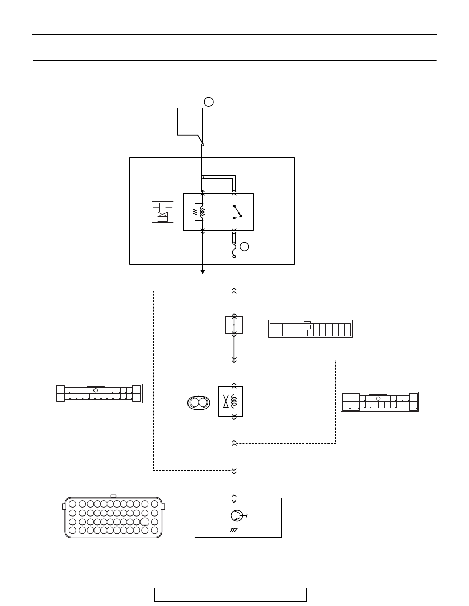
DTC P0446: Evaporative Emission Control System Vent Control Circuit

AK704280

1

3

2

4

2

8

7

6

5

4

3

11

21

20

19

18

17

16

15

14

13

12

9

22

1

10

2

1

6

5

4

3

17

16

15

14

13

12

11

10

7

18

1

2

9

8

71 72 73 74 75 76 77 78 79 80 81 82

83 84 85 86 87 88 89 90 91 92 93 94

95 96 97 98 99

100 101 102 103 104

112 113 114

109

108

107

110 111

115 116

106

105

118

117

1

12 13 14 15 16 1718 19 20 2122 2324

2 3 4 5

6 7 8 9 10 11

C-47

117

14

5

11

9

1

D-16

B-10

20A

WHITE

WHITE

RED-

BLUE

RED-

BLUE

BLUE

WHITE

A-34X

4

3

1

2

22

OFF

ON

AB

EVAPORATIVE EMISSION VENTILATION SOLENOID CIRCUIT

EVAPORATIVE EMISSION
VENTILATION SOLENOID

F-23

MU802779

13

36

FUSIBLE LINK

C-43

2

1

J/C (4)

RELAY BOX
(ENGINE COMPARTMENT)

ENGINE
CONTROL
MODULE

MFI
RELAY

TO ECM

RED-

GREEN

RED-

GREEN

RED-

GREEN

MULTIPORT FUEL INJECTION (MFI) DIAGNOSIS

TSB Revision

MULTIPORT FUEL INJECTION (MFI)

13A-442

.

CIRCUIT OPERATION

• The evaporative emission ventilation solenoid 

power is supplied from the MFI relay (terminal 
No. 2).

• The ECM controls the evaporative emission ven-

tilation solenoid ground by turning the power tran-
sistor in the ECM ON and OFF.

.

TECHNICAL DESCRIPTION

• To judge if there is open circuit in the evaporative 

emission ventilation solenoid drive circuit, ECM 
measures the surge voltage of the evaporative 
emission ventilation solenoid coil.

• The ECM drives the evaporative emission venti-

lation solenoid. After the solenoid is turned off, 
the ECM will check if the solenoid coil produces a 
surge voltage (battery positive voltage + 2 volts).

.

DESCRIPTIONS OF MONITOR METHODS

Off-surge does not occur after solenoid is operated 

on to off.

.

MONITOR EXECUTION

Continuous

.

MONITOR EXECUTION CONDITIONS 
(Other monitor and Sensor)

Other Monitor (There is no temporary DTC stored 

in memory for the item monitored below)

• Not applicable

Sensor (The sensor below is determined to be 

normal)

• Not applicable

.

AK704226

Connector: A-34X

MFI relay

A-34X

AB

AK704235 AB

Connector: B-10

ECM

B-10 (GR)

AK704281

Connectors: C-43, C-47

C-43 (B)

C-47

AB

AK704282

Connector: D-16

D-16

AB

AK704278

Evaporative emission 
ventilation solenoid

Canister
assembly

AB

Connector: F-23

F-23 (GR)

MULTIPORT FUEL INJECTION (MFI) DIAGNOSIS

TSB Revision

MULTIPORT FUEL INJECTION (MFI)

13A-443

DTC SET CONDITIONS
Logic Flow Chart

Check Conditions

• Engine is being cranked.
• Battery positive voltage is between 10 and 16.5 

volts.

Judgement Criteria

• The evaporative emission ventilation solenoid 

coil surge voltage (battery positive voltage + 2 
volts) is not detected for 0.2 second.

• The ECM monitors for this condition once during 

the drive cycle.

Check Conditions

• Battery positive voltage is between 10 and 16.5 

volts.

• ON duty cycle of the evaporative emission purge 

solenoid is 0 percent.

• Evaporative emission ventilation solenoid is ON.
• 1 second or more has elapsed after the above 

mentioned conditions have been met. 

Judgement Criterion

• The evaporative emission ventilation solenoid 

coil surge voltage (battery positive voltage + 2 
volts) is not detected for 1 second after the evap-
orative emission ventilation solenoid is turned 
OFF.

.

FAIL-SAFE AND BACKUP FUNCTION

• None

.

OBD-II DRIVE CYCLE PATTERN

Refer to Diagnostic Function − OBD-II Drive Cycle − 

Pattern 23 

P.13A-9

.

.

TROUBLESHOOTING HINTS (The most 
likely causes for this code to be set are:)

• Evaporative emission ventilation solenoid failed.
• Open or shorted evaporative emission ventilation 

solenoid circuit, harness damage, or connector 
damage.

• ECM failed.

End

No

No

Was surge voltage 

(> VB + 2V) detected?

Good

AK604339

Malfunction

Start

Yes

Yes

Monitoring
conditions

MULTIPORT FUEL INJECTION (MFI) DIAGNOSIS

TSB Revision

MULTIPORT FUEL INJECTION (MFI)

13A-444

DIAGNOSIS

Required Special Tools:

• MB991958: Scan tool (M.U.T.-III Sub Assembly)

• MB991824: V.C.I.
• MB991827: USB Cable
• MB991910: Main Harness A

• MB992110: Power Plant ECU Check Harness

STEP 1. Using scan tool MB991958, check actuator test 
item 15: Evaporative Emission Ventilation Solenoid.

CAUTION

To prevent damage to scan tool MB991958, always turn the 
ignition switch to the "LOCK" (OFF) position before con-
necting or disconnecting scan tool MB991958.
(1) Connect scan tool MB991958 to the data link connector.
(2) Turn the ignition switch to the "ON" position.
(3) Set scan tool MB991958 to the actuator test mode for item 

15, Evaporative emission ventilation solenoid.

• An operation sound should be heard and vibration 

should be felt when the evaporative emission ventilation 
solenoid is operated.

(4) Turn the ignition switch to the "LOCK" (OFF) position.
Q: Is the solenoid operating properly?

YES : It can be assumed that this malfunction is intermittent. 

Refer to GROUP 00, How to Use 
Troubleshooting/Inspection Service Points − How to 

Cope with Intermittent Malfunctions 

P.00-15

.

NO :  Go to Step 2.

STEP 2. Check harness connector F-23 at the evaporative 
emission ventilation solenoid for damage.
Q: Is the harness connector in good condition?

YES : Go to Step 3.
NO :  Repair or replace it. Refer to GROUP 00E, Harness 

Connector Inspection 

P.00E-2

. Then go to Step 10.

AC608435

Data link connector

MB991827

MB991824

MB991910

AB


Content   ..  342  343  344  345   ..