Mitsubishi Lancer Evolution X. Manual - part 341


  Index      Mitsubishi     Mitsubishi Lancer Evolution X GS41EVO - service repair manual 2008 year


Search            


Content   ..  339  340  341  342   ..


Mitsubishi Lancer Evolution X. Manual - part 341


MULTIPORT FUEL INJECTION (MFI) DIAGNOSIS

TSB Revision

MULTIPORT FUEL INJECTION (MFI)

13A-429

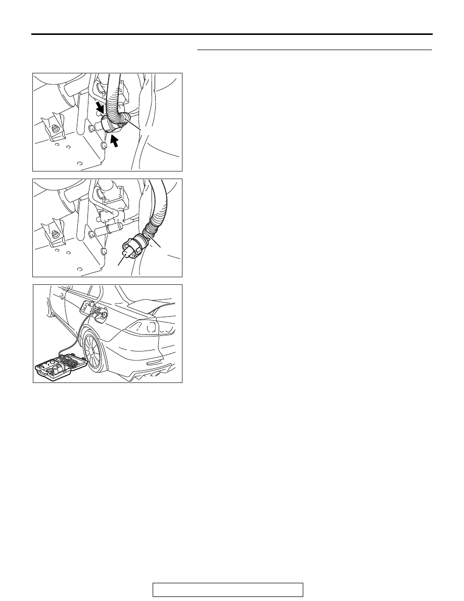
STEP 7. Perform the pressure test on the evaporative 
emission system.
(1) Disconnect hose E from the canister while holding the 

release buttons indicated in the illustration pressed by 
fingers.

(2) Plug the disconnected end of hose E.
(3) Confirm that the evaporative emission system pressure 

pump (Miller number 6872A) is operating properly. Perform 
the self-test as described in the pump manufacturer's 
instructions.

(4) Remove the fuel cap.

(5) Connect the evaporative emission system pressure pump 

(Miller number 6872A) to the fuel tank filler tube by using 
fuel tank adapter (MLR-8382).

(6) Pressure test the system to determine whether any leaks 

are present.
NOTE: The "Pressure test" in this procedure refers to the 
I/M240 Simulation Test. The eight steps of this test are 
described in the manufacturer's instructions for the evapo-
rative emission system pressure pump, Miller number 
6872A.

(7) Remove the evaporative emission system pressure pump 

(Miller number 6872A) and the fuel tank adapter 
(MLR-8382), and reinstall the fuel cap.

(8) Connect hose E to the evaporative emission canister.
Q: Is the evaporative emission system line free of leaks?

YES : Go to Step 12 .
NO :  Go to Step 8 .

AK704691

AB

Hose E

AK704692 AB

Plug

Hose E

AK704700

MULTIPORT FUEL INJECTION (MFI) DIAGNOSIS

TSB Revision

MULTIPORT FUEL INJECTION (MFI)

13A-430

STEP 8. Check for leaks in evaporative emission hoses E 
and F.

Use a hand vacuum pump to test each hose E and F.

Q: Do the hoses hold vacuum?

YES : Go to Step 9 .
NO :  Replace any damaged hose. Then go to Step 14 .

STEP 9. Check for leaks in evaporative emission hoses G 
and H.
(1) Remove the fuel tank assembly.
(2) Use a hand vacuum pump to test each hose G and H.
Q: Do the hoses hold vacuum?

YES : Go to Step 10.
NO :  Replace any damaged hose and reinstall the fuel tank 

assembly. Then go to Step 14 .

STEP 10. Check for leaks in evaporative emission hoses I 
and J.
(1) Remove the fuel tank assembly.
(2) Use a hand vacuum pump to test each hose I and J.
Q: Do the hoses hold vacuum?

YES : Go to Step 11 .
NO :  Replace any damaged hose and reinstall the fuel tank 

assembly. Then go to Step 14 .

AK704693AB

Hose E

AK704694

AB

Hose F

AK704696

Hose G

Hose H

AB

AK704697

Hose J

Hose I

AC

MULTIPORT FUEL INJECTION (MFI) DIAGNOSIS

TSB Revision

MULTIPORT FUEL INJECTION (MFI)

13A-431

STEP 11. Check for leaks in the fuel tank.
(1) Visually check for cracks or other leaks in the fuel tank.

NOTE: Carefully check the fuel pump module and the fuel 
tank differential pressure sensor installation in the fuel tank.

(2) Connect the evaporative emission system pressure pump 

(Miller number 6872A) to the fuel filler hose.

(3) Plug the hose and the nipple shown in the illustration.

NOTE: If these items are not securely plugged now, the fuel 
could leak in the next step.

(4) Pressurize the fuel tank with the evaporative emission 

system pressure pump.

(5) In the pressurized state, check for leaks by applying a 

soapy water solution to each section and look for bubbles.

Q: Are any leaks found?

YES <When there is a leak from the attachment points of 
the fuel pump module, fuel tank differential pressure 
sensor, fuel level sensor or leveling valve.> : 

Reassemble the leaked parts and check again that 
there are no leaks. Then reinstall the fuel tank. Then 
go to Step 14 .

YES <When there is a leak from the fuel tank.> : Replace 

the fuel tank. Then go to Step 1.

NO :  When there is no leak, reinstall the fuel tank. Then go 

to Step 13 .

AK704698

AK704701

AK704701AB

MULTIPORT FUEL INJECTION (MFI) DIAGNOSIS

TSB Revision

MULTIPORT FUEL INJECTION (MFI)

13A-432

STEP 12. Check the evaporative emission canister for 
vacuum leaks.
(1) Connect a hand vacuum pump to the evaporative emission 

canister and plug the other nipples.

(2) Apply a pressure on the hand vacuum pump, and confirm 

that air is maintained.

(3) Disconnect the hand vacuum pump and remove the plugs.
Q: Is the evaporative emission canister in good condition?

YES : Go to Step 13 .
NO :  Replace the evaporative emission canister. Then go 

to Step 14 .

STEP 13. Using scan tool MB991958, check the 
evaporative emission system monitor test.

CAUTION

• During this test, the ECM automatically increases the 

engine speed to 1,600 r/min or greater. Check that the 
transaxle is set to "P" position.

(1) Turn the ignition switch to the "ON" position.
(2) Erase the DTCs using scan tool MB991958.
(3) Check that the fuel cap is securely closed (Tighten until 

three clicks are heard).

(4) Start the engine.
(5) Select "Special Function"
(6) Select "Evap Leak Monitor"
(7) During the test, keep the accelerator pedal at the idle 

position.

(8) Keep the engine speed and engine load within the specified 

range. When the monitor test starts, the "In Progress" item 
on scan tool MB991958 will change from "NO" to "YES".

(9) Turn the ignition switch to the "LOCK" (OFF) position. 
Q: Is "Evap Leak Mon. Completed. Test Failed and DTCs 

Set" displayed on scan tool MB991958?
YES : 
Replace the ECM. When the ECM is replaced, 

register the ID code. Refer to GROUP 42B, ID Code 
Registration Judgment Table <Vehicles with KOS> 

P.42B-11

 or GROUP 42C, ID Code Registration 

Judgment Table <Vehicles with WCM> 

P.42C-9

. Then 

go to Step 14 .

NO <"Evap Leak Mon. Completed. Test Passed" is 
displayed on scan tool MB991958.> : 
The evaporative 

emission system is working properly at this time. Go 
to Step 14   .

NO <"Evap Leak Mon. Discontinued. Retest again from 
the first" is displayed on scan tool MB991958.> : 
The 

EVAP monitor has been interrupted during the test. 
Turn the ignition switch to the "LOCK" (OFF) position 
once, and repeat the monitoring.

AK704702

AB

Plugs

AB


Content   ..  339  340  341  342   ..