Mitsubishi Lancer Evolution X. Manual - part 316
MULTIPORT FUEL INJECTION (MFI) DIAGNOSIS
TSB Revision
MULTIPORT FUEL INJECTION (MFI)
13A-329
.
CIRCUIT OPERATION
• The injector power is supplied from the injector
relay (terminal No. 3).
• The ECM controls the injector by turning the
power transistor in the ECM "ON" and "OFF".
.
TECHNICAL DESCRIPTION
• The amount of fuel injected by the injector is con-
trolled by the amount of continuity time the coil is
grounded by the ECM.
.
DESCRIPTIONS OF MONITOR METHODS
The ECM detects open circuit and short malfunction.
.
MONITOR EXECUTION
Continuous
.
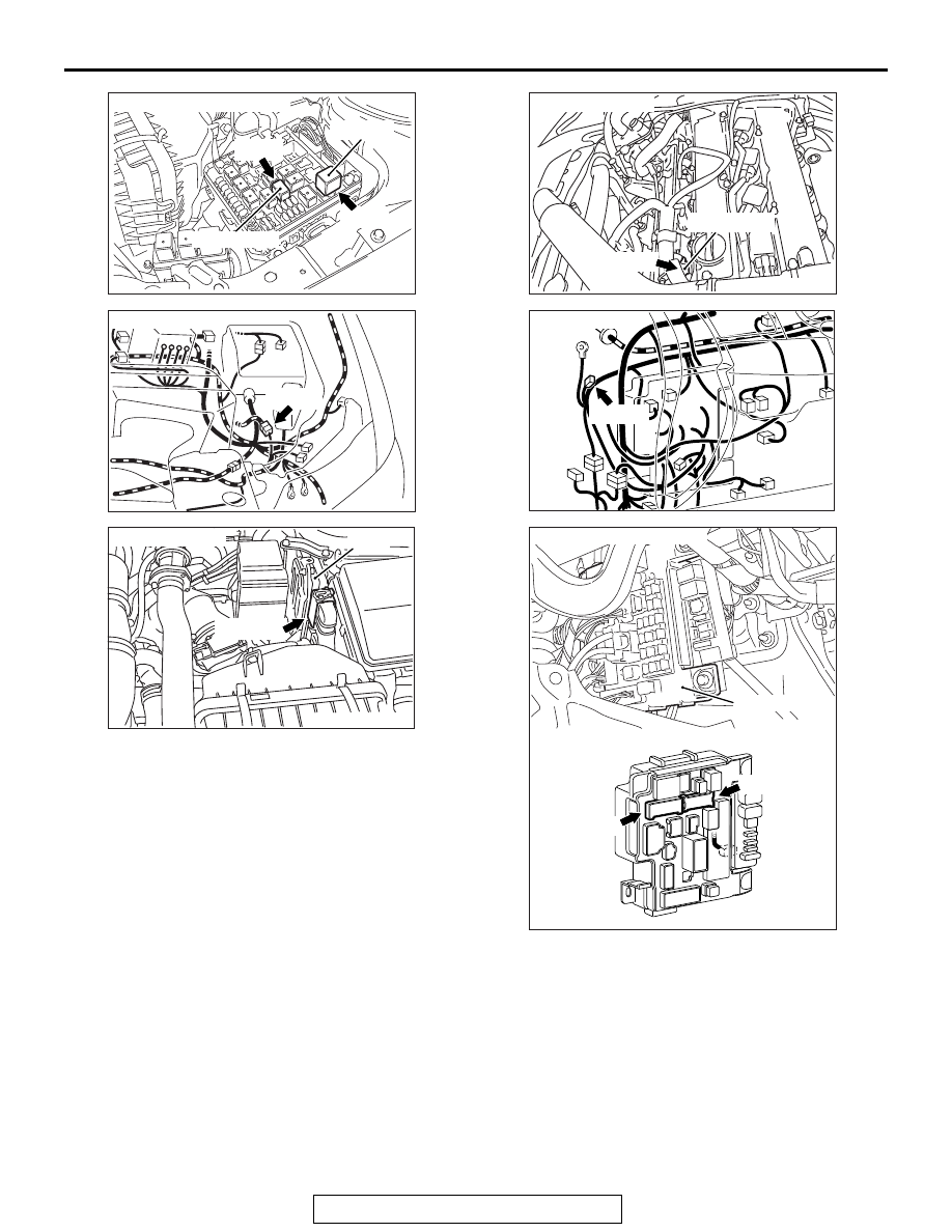
AK704256
Connectors: A-25X, A-34X
MFI relay
Injector relay
A-34X
A-25X
AB
AK704255AB
Connector: A-39
A-39 (B)
AK704227
Connector: B-09
ECM
B-09 (GR)
AB
AK704266 AB
Connector: B-104
B-104 (GR)
Injector No. 4
AK704258 AB
Connector: C-50
C-50 (B)
AK704259AB
Connectors: C-304, C-317
ETACS-ECU
C-304
C-317