Mitsubishi Lancer Evolution X. Manual - part 265


  Index      Mitsubishi     Mitsubishi Lancer Evolution X GS41EVO - service repair manual 2008 year


Search            


Content   ..  263  264  265  266   ..


Mitsubishi Lancer Evolution X. Manual - part 265


MULTIPORT FUEL INJECTION (MFI) DIAGNOSIS

TSB Revision

MULTIPORT FUEL INJECTION (MFI)

13A-125

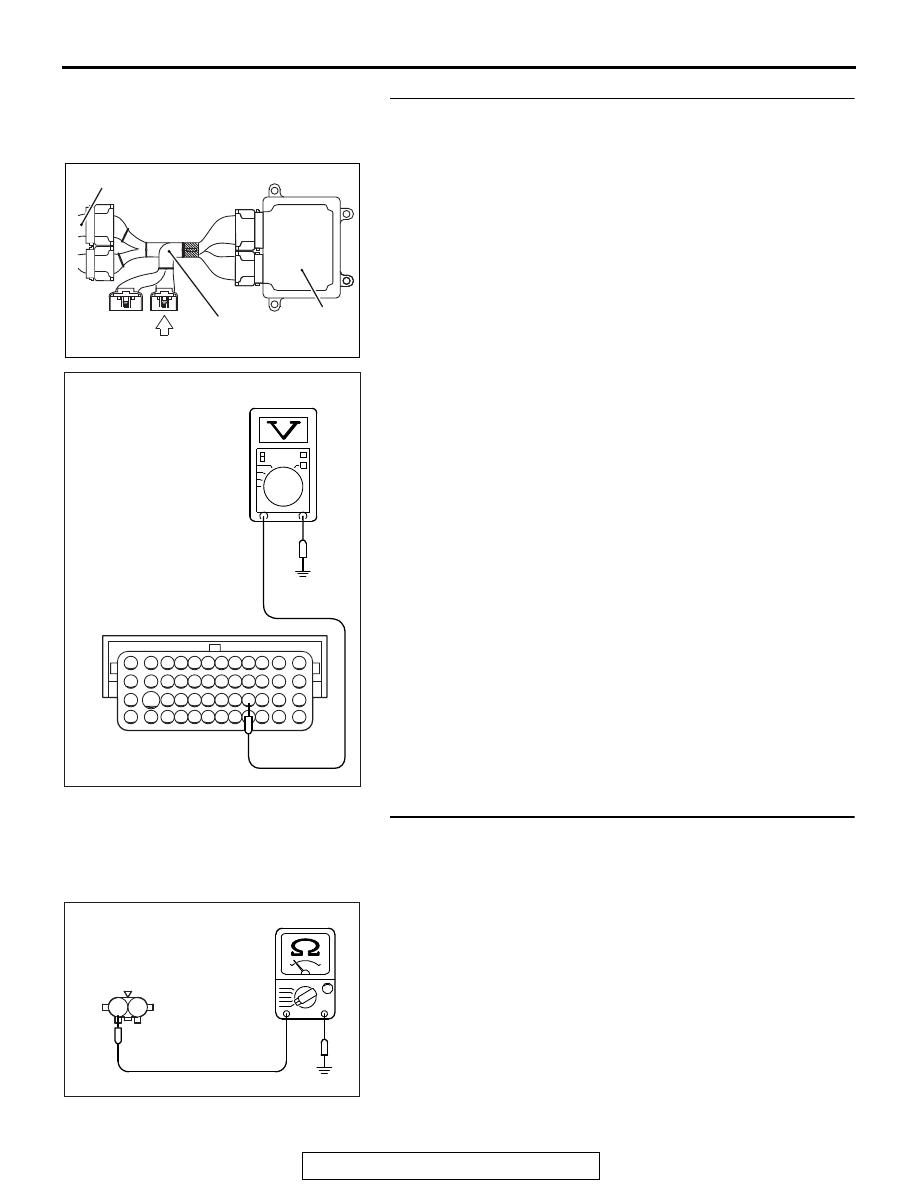
STEP 6. Measure the sensor supply voltage at ECM 
connector B-10 by using power plant ECU check harness 
special tool MB992110.
(1) Disconnect all ECM connectors. Connect the power plant 

ECU check harness special tool MB992110 between the 
separated connectors.

(2) Disconnect the intake air temperature sensor 2 connector 

B-16.

(3) Turn the ignition switch to the "ON" position.

(4) Measure the voltage between terminal No. 98 and ground.

• Voltage should be between 4.5 and 4.9 volts.

(5) Turn the ignition switch to the "LOCK" (OFF) position.
Q: Is the measured voltage between 4.5 and 4.9 volts?

YES : Check harness connector A-13 at intermediate 

connector for damage, and repair or replace as 
required. Refer to GROUP 00E, Harness Connector 
Inspectio

P.00E-2

. If intermediate connector is in 

good condition, repair harness wire between intake air 
temperature sensor 2 connector B-16 (terminal No. 1) 
and ECM connector B-10 (terminal No. 98) because 
of open circuit. Then go to Step 10. 

NO :  Replace the ECM. When the ECM is replaced, 

register the ID code. Refer to GROUP 42B, ID Code 
Registration Necessity Judgment Table <Vehicles 
with KOS> 

P.42B-11

 or GROUP 42C, ID Codes 

Registration Judgment Table <Vehicles with WCM> 

P.42C-9

. Then go to Step 10. 

STEP 7. Check the continuity at intake air temperature 
sensor 2 harness side connector B-16.
(1) Disconnect the connector B-16 and measure at the harness 

side.

(2) Check for the continuity between terminal No. 2 and 

ground.

• Continuity (2 ohms or less)

Q: Does continuity exist?

YES : Replace the ECM. When the ECM is replaced, 

register the ID code. Refer to GROUP 42B, ID Code 
Registration Necessity Judgment Table <Vehicles 
with KOS> 

P.42B-11

 or GROUP 42C, ID Codes 

Registration Judgment Table <Vehicles with WCM> 

P.42C-9

. Then go to Step 10.

NO :  Go to Step 8.

AK604171

ECM

AB

Body side harness 

MB992110

82 81 80 79 78 77 76 75 74 73 72 71

94 93 92 91 90 89 88 87 86 85 84 83

99 98 97 96 95

100

101

102

103

104

105

106

112

113

114

109 108

107

110

111

115

116

117

118

AK704403 AB

Power plant ECU
check harness connector

1

2

AK704401

B-16 harness 
connector: 
component side

AB

MULTIPORT FUEL INJECTION (MFI) DIAGNOSIS

TSB Revision

MULTIPORT FUEL INJECTION (MFI)

13A-126

STEP 8. Check harness connector B-10 at ECM for 
damage.
Q: Is the harness connector in good condition?

YES : Go to Step 9.
NO :  Repair or replace it. Refer to GROUP 00E, Harness 

Connector Inspection 

P.00E-2

. Then go to Step 10.

STEP 9. Check for open circuit between intake air 
temperature sensor 2 connector B-16 (terminal No. 2) and 
ECM connector B-10 (terminal No. 97).
NOTE: Check harness after checking intermediate connector 
A-13. If intermediate connector is damaged, repair or replace it. 
Repair to GROUP 00E, Harness Connector Inspection 

P.00E-2

. Then go to Step 10.

Q: Is the harness wire in good condition?

YES : Replace the ECM. When the ECM is replaced, 

register the ID code. Refer to GROUP 42B, ID Code 
Registration Necessity Judgment Table <Vehicles 
with KOS> 

P.42B-11

 or GROUP 42C, ID Codes 

Registration Judgment Table <Vehicles with WCM> 

P.42C-9

. Then go to Step 10.

NO :  Repair it. Then go to Step 10.

STEP 10. Test the OBD-II drive cycle.
(1) Carry out a test drive with the drive cycle pattern. Refer to 

Diagnostic Function − OBD-II Drive Cycle − Pattern 23 

P.13A-9

.

(2) Check the diagnostic trouble code (DTC).
Q: Is DTC P0098 set?

YES : Retry the troubleshooting.
NO :  The inspection is complete.

MULTIPORT FUEL INJECTION (MFI) DIAGNOSIS

TSB Revision

MULTIPORT FUEL INJECTION (MFI)

13A-127

DTC P0101: Mass Airflow Circuit Range/Performance Problem

AK704233

71 72 73 74 75 76 77 78 79 80 81 82

83 84 85 86 87 88 89 90 91 92 93 94

95 96 97 98 99

100 101 102 103 104

112 113 114

109

108

107

110 111

115 116

106

105

118

117

1

3

2

4

3 4

2

1

AB

MASS AIRFLOW SENSOR CIRCUIT

MASS AIRFLOW SENSOR

87

88

3

2

HEAT
SENSITIZING
RESISTANCE

BLUE

A-07

(MU805110)

4

20A

WHITE

WHITE

WHITE

A-34X

4

3

1

2

22

B-10

36

FUSIBLE LINK

OFF

ON

RELAY BOX
(ENGINE COMPARTMENT)

ENGINE
CONTROL
MODULE

TO ECM

MFI
RELAY

BLA

CK-BLUE

MULTIPORT FUEL INJECTION (MFI) DIAGNOSIS

TSB Revision

MULTIPORT FUEL INJECTION (MFI)

13A-128

.

CIRCUIT OPERATION

• The mass airflow sensor power is supplied from 

the MFI relay (terminal No. 2), and the ground is 
provided on the ECM (terminal No. 88).

• A voltage that is according to the mass airflow 

rate is sent to the ECM (terminal No. 87) from the 
mass airflow sensor output terminal (terminal No. 
3).

.

TECHNICAL DESCRIPTION

• While the engine is running, the mass airflow 

sensor outputs electric current which corre-
sponds to the mass airflow rate.

• The ECM converts the electric current into the 

voltage and checks whether the voltage is within 
a specified range while the engine is running.

.

DESCRIPTIONS OF MONITOR METHODS

Compare load value with mass airflow sensor output 

voltage.

.

MONITOR EXECUTION

Continuous

.

MONITOR EXECUTION CONDITIONS 
(Other monitor and Sensor)

Other Monitor (There is no temporary DTC stored 

in memory for the item monitored below)

• Not applicable

Sensor (The sensor below is determined to be 

normal)

• Throttle position sensor

.

AK704234

Connector: A-07

Mass airflow sensor

A-07 (GR)

AB

AK704226

Connector: A-34X

MFI relay

A-34X

AB

AK704235 AB

Connector: B-10

ECM

B-10 (GR)


Content   ..  263  264  265  266   ..