Mitsubishi Lancer Evolution X. Manual - part 258
MULTIPORT FUEL INJECTION (MFI) DIAGNOSIS
TSB Revision
MULTIPORT FUEL INJECTION (MFI)
13A-97
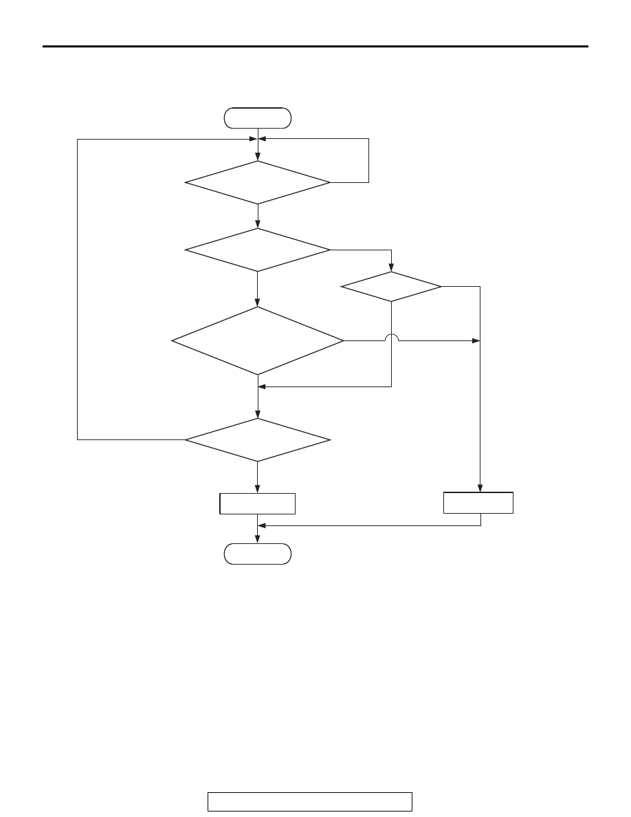
DTC SET CONDITIONS
Logic Flow Chart
.
Check Conditions
• More than 2 seconds have passed since the
engine starting sequence was completed.
• While the heated oxygen sensor (rear) heater is
on.
• Battery positive voltage is between 11 and 16.5
volts.
Judgement Criterion
• The heated oxygen sensor (rear) heater current
has continued to be lower than 0.17 ampere for 2
seconds.
Check Conditions
• More than 2 seconds have passed since the
engine starting sequence was completed.
• While the heated oxygen sensor (rear) heater is
off.
• Battery positive voltage is between 11 and 16.5
volts.
Judgement Criterion
• The heated oxygen sensor (rear) heater voltage
has continued to be lower than 2.0 volts for 2 sec-
onds.
.
End
No
No
Malfunction
Good
Current < 0.17A
or
Current > 10.5A
Voltage < 2.0V
AK900352
Heater activation
command ON
No
No
Start
Yes
Yes
Yes
Yes
Yes
No
Continuous
failure for 2secs
Monitoring
conditions