Mitsubishi Lancer Evolution X. Manual - part 233
POWER STEERING HOSES
TSB Revision
POWER STEERING
37-47
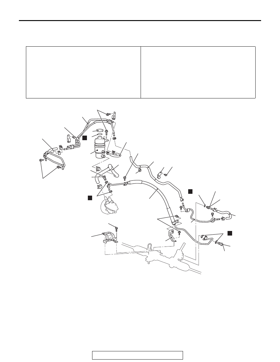
POWER STEERING HOSES
REMOVAL AND INSTALLATION
M1372005701973
Pre-removal Operation
• Power Steering Fluid Draining (Refer to
.)
• Front Bumper and Radiator Grille Assembly Removal
(Refer to GROUP 51 − Front Bumper Assembly and Radi-
ator Grille
.)
• Headlight (RH) Removal (Refer to GROUP 54A − Head-
light
• Strut Tower Bar Removal (Refer to GROUP 42A − Strut
Tower Bar
.)
Post-installation Operation
• Strut Tower Bar Installation (Refer to GROUP 42A − Strut
Tower Bar
.)
• Headlight (RH) Installation (Refer to GROUP 54A − Head-
light
• Front Bumper and Radiator Grille Assembly Installation
(Refer to GROUP 51 − Front Bumper Assembly and Radi-
ator Grille
.)
• Power Steering Fluid Refilling and Bleeding (Refer to
AC900205 AC
13 ± 2 N·m
10 ± 1 ft-lb
13
5
N
6
7
N
N
8
4
19
18
14
9
20
21
11
12
15
13 ± 2 N·m
10 ± 1 ft-lb
13 ± 2 N·m
10 ± 1 ft-lb
57 ± 7 N·m
42 ± 5 ft-lb
57 ± 7 N·m
42 ± 5 ft-lb
15 ± 3 N·m
11 ± 2 ft-lb
13 ± 2 N·m
10 ± 1 ft-lb
13 ± 2 N·m
10 ± 1 ft-lb
13 ± 2 N·m
10 ± 1 ft-lb
10
5.0 ± 2.0 N·m
44 ± 18 in-lb
16
17
N
1
3
2
Removal steps
1.
Cap
2.
Oil reservoir
3.
O-ring
>>
D
<<
4.
Suction hose
5.
Eye bolt
6.
Gasket
7.
Eye bolt
8.
Gasket
>>
C
<<
9.
Pressure hose assembly
10. Heat protector
11. Pressure hose bracket
>>
B
<<
12. Return hose
13. Return tube assembly
14. Gasket
15. Return tube
>>
B
<<
16. Clip
>>
B
<<
17. Hose clamp
>>
B
<<
18. Return hose
>>
B
<<
19. Return hose
20. Return tube assembly
>>
A
<<
21. Cooler tube assembly
Removal steps (Continued)