Mitsubishi Lancer Evolution X. Manual - part 200


  Index      Mitsubishi     Mitsubishi Lancer Evolution X GS41EVO - service repair manual 2008 year


Search            


Content   ..  198  199  200  201   ..


Mitsubishi Lancer Evolution X. Manual - part 200


DIAGNOSIS

TSB Revision

ACTIVE STABILITY CONTROL SYSTEM (ASC)

35C-265

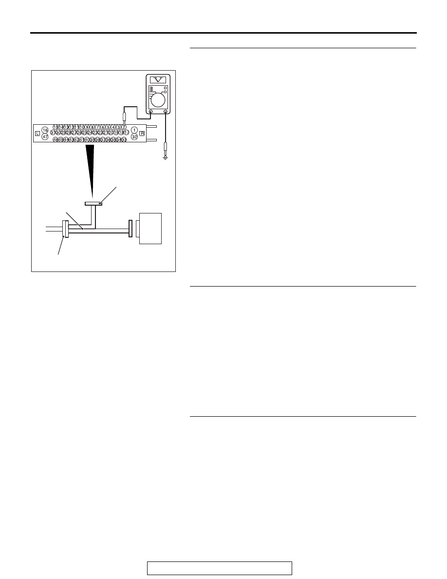
STEP 16. Voltage measurement at A-05 ASC-ECU 
connector
(1) Disconnect the connector, connect the ASC check harness 

(Special tool: MB991997) to the wiring harness-side 
connector, and measure the voltage at the special tool 
connector side.
NOTE: Do not connect the special tool to ASC-ECU.

(2) Measure the voltage between the terminal No. 2 and the 

body ground.

OK: Battery positive voltage

Q: Is the check result normal?

YES : Go to Step 20.
NO :  Go to Step 17.

STEP 17. Measure the voltage at the C-309 ETACS-ECU 
connector.
(1) Disconnect the connector, and measure at the wiring 

harness-side connector.

(2) Measure the voltage between the terminal No. 1 and the 

body ground.

OK: Battery positive voltage

Q: Is the check result normal?

YES : Go to Step 18.
NO :  Repair the wiring harness between C-309 

ETACS-ECU connector terminal No. 1 and the fusible 
link No. 34.

STEP 18. Measure the voltage at the C-315 ETACS-ECU 
connector.
(1) Without disconnecting the connector, measure by 

backprobing.

(2) Measure the voltage between the terminal No. 4 and the 

body ground.

OK: Battery positive voltage

Q: Is the check result normal?

YES : Go to Step 20.
NO :  Go to Step 19.

AC400817CN

ASC-ECU

MB991997

A-05 ASC-ECU 
harness connector

Check harness

DIAGNOSIS

TSB Revision

ACTIVE STABILITY CONTROL SYSTEM (ASC)

35C-266

STEP 19. Wiring harness check between A-05 ASC-ECU 
connector terminal No. 2 and C-315 ETACS-ECU connector 
terminal No. 4

• Check for open circuit.

Q: Is the check result normal?

YES : Go to Step 20.
NO  :  Repair the wiring harness.

STEP 20. Resistance measurement at A-05 ASC-ECU 
connector
(1) Disconnect the connector, connect the ASC check harness 

(Special tool: MB991997) to the wiring harness-side 
connector, and measure the voltage at the special tool 
connector side.
NOTE: Do not connect the special tool to ASC-ECU.

(2) Measure the resistance between the terminal No. 16 and 

the body ground as well as between the terminal No. 47 
and the body ground.

OK: Continuity exists (2 Ω or less)

Q: Is the check result normal?

YES : Go to Step 21.
NO  :  Repair the wiring harness.

STEP 21. Retest the system.
Q: Is the communication with scan tool MB991958 

possible?
YES : 
Intermittent malfunction. (Refer to GROUP 00 − How 

to Cope with Intermittent Malfunction 

P.00-15

.)

NO :  Check that the scan tool connection cable is properly 

connected, and that the V.C.I. switch is turned ON. 
Then, replace the hydraulic unit (integrated with 
ASC-ECU).(Refer to 

P.35C-298

.) Then go to Step 22.

STEP 22. Retest the system.
Q: Is the communication with scan tool MB991958 

possible?
YES : 
Return to Step 1.
NO :  This diagnosis is complete.

AC400817CO

ASC-ECU

MB991997

A-05 ASC-ECU 
harness connector

Check harness

DIAGNOSIS

TSB Revision

ACTIVE STABILITY CONTROL SYSTEM (ASC)

35C-267

Inspection Procedure 12: ABS/skid control/TCL operates too frequently.

CAUTION

• If there is any problem in the CAN bus lines, an incor-

rect diagnostic trouble code may be set. Prior to this 
diagnosis, diagnose the CAN bus lines.

• Whenever the ECU is replaced, ensure that the CAN 

bus lines are normal.

.

COMMENTS ON TROUBLE SYMPTOM

• Although it is difficult to determine the trouble cause since it 

depends on the running status and road surface condition, 
a malfunction of hydraulic circuit may be present if no diag-
nostic trouble code is detected.

• If a wheel or tire of other than the genuine specified size is 

mounted, the ABS/skid control/TCL may be activated pre-
maturely.

• If non-genuine braking device or non-genuine impact reduc-

ing device is mounted, the ABS/skid control/TCL may be 
activated prematurely.

.

PROBABLE CAUSES

• Installation of wheel or tire other than genuine specified size
• Tire pressure abnormality
• Tire wear and deterioration
• Installation of non-genuine braking device or non-genuine 

impact reducing device

• Wheel alignment abnormality
• Malfunction of brake-related components
• Malfunction of wheel speed sensor
• Malfunction of G and yaw rate sensor
• Malfunction of steering wheel sensor
• Malfunction of hydraulic unit (integrated with ASC-ECU)
• Malfunction of hydraulic circuit
• External noise interference

DIAGNOSIS

Required Special Tools:

• MB991958 Scan Tool (M.U.T.-III Sub Assembly)

• MB991824: Vehicle Communication Interface (V.C.I.)
• MB991827 M.U.T.-III USB Cable
• MB991910 M.U.T.-III Main Harness A

• MB991997: ASC check harness

DIAGNOSIS

TSB Revision

ACTIVE STABILITY CONTROL SYSTEM (ASC)

35C-268

STEP 1. Check of wheels and tires
Perform the following checks.

• Check of wheel and tire size
• Tire wear and deterioration
• Tire pressure check

NOTE: For the tire pressure, refer to the tire pressure label 
attached to the lower section of driver's side door striker.

Q: Is the check result normal?

YES : Go to Step 2.
NO :  Correct the wheels and tires. Then go to Step 9.

STEP 2. Check the DTC.
Using scan tool, check the diagnostic trouble code for ASC sys-
tem. (Refer to 

P.35C-22

.)

Q: Is the check result normal?

YES : Go to Step 3.
NO :  Carry out the diagnosis for the DTC. (Refer to 

P.35C-22

.) Then go to Step 9.

STEP 3. Check of brake-related components other than 
hydraulic unit (integrated with ASC-ECU)
Perform the following checks, and also check that no non-gen-
uine parts are installed.

• Brake pad check (Refer to GROUP 35A − On-vehicle Ser-

vice, Brake Pad Check 

P.35A-18

.)

• Brake disc runout check (Refer to GROUP 35A − On-vehicle 

Service, Brake Disc Rotor Check 

P.35A-21

.)

• Brake drag force check (Refer to GROUP 35A − On-vehicle 

Service, Brake Drag Force Check 

P.35A-23

.)

Q: Is the check result normal?

YES : Go to Step 4.
NO :  Repair or replace the trouble spot. Then go to Step 9.

STEP 4. Wheel alignment check
Perform the following checks, and also check that no non-gen-
uine parts are installed.

• Front wheel alignment check (Refer to GROUP 33 − 

On-vehicle Service, Front Wheel Alignment Check and 
Adjustment 

P.33-8

.)

• Rear wheel alignment check (Refer to GROUP 34 − 

On-vehicle Service, Rear Wheel Alignment Check and 
Adjustment 

P.34-9

.)

Q: Is the check result normal?

YES : Go to Step 5.
NO :  Repair or replace the trouble spot. Then go to Step 9.


Content   ..  198  199  200  201   ..