Mitsubishi Lancer Evolution X. Manual - part 159


  Index      Mitsubishi     Mitsubishi Lancer Evolution X GS41EVO - service repair manual 2008 year


Search            


Content   ..  157  158  159  160   ..


Mitsubishi Lancer Evolution X. Manual - part 159


DIAGNOSIS

TSB Revision

ACTIVE STABILITY CONTROL SYSTEM (ASC)

35C-101

STEP 16. Check whether the DTC is reset.
Drive the vehicle at 12mph (20 km/h) or more.
NOTE: The ABS warning light does not turn OFF in some 
cases unless the vehicle runs at 12mph (20 km/h) or higher.
Q: Is DTC C1046 set?

YES : Replace the hydraulic unit (incorporates in 

ASC-ECU).(Refer to 

P.35C-298

.) Then go to Step 17.

NO :  Intermittent malfunction. (Refer to GROUP 00 − How 

to Cope with Intermittent Malfunction 

P.00-15

.)

STEP 17. Check whether the DTC is reset.
Drive the vehicle at 12mph (20 km/h) or more.
NOTE: The ABS warning light does not turn OFF in some 
cases unless the vehicle runs at 12mph (20 km/h) or higher.
Q: Is DTC C1046 set?

YES : Return to Step 1.
NO :  This diagnosis is complete.

DTC C1047: FR wheel speed sensor control phase time exceeded
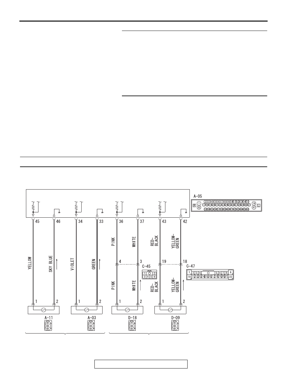
ASC-ECU

(LH)

(LH)

(RH)

(RH)

FRONT WHEEL SPEED SENSOR

REAR WHEEL SPEED SENSOR

Wheel Speed Sensor Circuit

AC804587

DIAGNOSIS

TSB Revision

ACTIVE STABILITY CONTROL SYSTEM (ASC)

35C-102

CAUTION

• If there is any problem in the CAN bus lines, an incor-

rect diagnostic trouble code may be set. Prior to this 
diagnosis, diagnose the CAN bus lines.

• Whenever the ECU is replaced, ensure that the CAN 

bus lines are normal.

• When the hydraulic unit (integrated with ASC-ECU) is 

replaced, always perform the calibration of steering 
wheel sensor, G and yaw rate sensor, brake fluid pres-
sure sensor, cut valve, and inlet valve.(Refer to 

P.35C-287

P.35C-289

P.35C-294

, and 

P.35C-295

.)

.

CIRCUIT OPERATION

• Each wheel speed detecting section is a kind of a pulse 

generator. It consists of the encoder (plate on which the 
north and south pole of magnet are arranged alternately) for 
detecting the wheel speed, which rotates at the same speed 
of the wheels, and the wheel speed sensor. This detecting 
section outputs the frequency pulse signals in proportion to 
the wheel speed.

• The pulse signals generated by the wheel speed detecting 

section are sent to ASC-ECU. ASC-ECU uses the fre-
quency of the pulse signals to determine the wheel speed.

.

DTC SET CONDITIONS

This diagnostic trouble code is set if any malfunction below is 
detected.

• When the brake fluid pressure is decreased for a long time.
• When the brake fluid pressure is held for a long time.

NOTE: ABS controls the vehicle based on the wheel speed sig-
nal. When the brake fluid pressure is decreased or held for an 
abnormally long time, the wheel speed sensor signal may have 
a problem.

.

PROBABLE CAUSES

• Damaged wiring harness and connectors
• External noise interference
• Malfunction of wheel speed sensor
• ABS-ECU malfunction

AC708948

A-05 (B)

AC

Connectors: A-03, A-05

A-03 (B)

DIAGNOSIS

TSB Revision

ACTIVE STABILITY CONTROL SYSTEM (ASC)

35C-103

• Excessive gap between the wheel speed sensor and the 

wheel speed detection encoder

• Adhesion of foreign materials on the wheel speed sensor
• Adhesion of foreign materials on the wheel speed detection 

encoder

• Wheel bearing malfunction
• Improper installation of the wheel speed sensor
• Deformation of the wheel speed detection encoder
• Disturbance of magnetization pattern for wheel speed 

detection encoder

• Missing teeth of the wheel speed detection encoder

DIAGNOSIS

Required Special Tools:

• MB991958 Scan Tool (M.U.T.-III Sub Assembly)

• MB991824: Vehicle Communication Interface (V.C.I.)
• MB991827 M.U.T.-III USB Cable
• MB991910 M.U.T.-III Main Harness A

• MB991997: ASC check harness

STEP 1. Using scan tool MB991958, diagnose the CAN bus 
lines.
Using scan tool MB991958, diagnose the CAN bus lines.
Q: Is the check result normal?

YES : Go to Step 3.
NO :  Repair the CAN bus lines. (Refer to GROUP 54C − 

Troubleshooting 

P.54C-15

.) After repairing the CAN 

bus line, go to Step 2.

STEP 2. DTC recheck after repairing the CAN bus line
Q: Is DTC C1047 set?

YES : Go to Step 3.
NO :  This diagnosis is complete.

STEP 3. Scan tool diagnostic trouble code
Check that the diagnostic trouble codes No. C1015, C101C, 
C101F, and C1042 are simultaneously set.
Q: Are DTC C1015, C101C, C101F, and C1042 also set?

YES : Carry out the diagnosis for the diagnostic trouble 

codes that are set, and then go to Step 5.

NO :  Go to Step 4.

STEP 4. Scan tool service data
Check the following service data. (Refer to 

P.35C-276

.)

• Item No.02: FR wheel speed sensor

Q: Is the check result normal?

YES : Go to Step 16.
NO :  Go to Step 5.

DIAGNOSIS

TSB Revision

ACTIVE STABILITY CONTROL SYSTEM (ASC)

35C-104

STEP 5. Voltage measurement at A-05 ASC-ECU connector
(1) Disconnect the ASC-ECU connector, connect the special 

tool ASC check harness (MB991997) to the wiring 
harness-side connector, and then measure at the special 
tool connector side.
NOTE: Do not connect the special tool to ASC-ECU.

(2) Turn the ignition switch to the ON position.
(3) Measure the voltage between the wheel speed sensor 

power supply terminal (signal terminal) No. 34 and the body 
ground as well as between the ground terminal No. 33 and 
the body ground.

OK: 1 volt or less

Q: Is the check result normal?

YES  : Go to Step 6.
NO (Not normal at terminal 34 or 33) : Go to Step 7.

STEP 6. Resistance measurement at A-05 ASC-ECU 
connector
(1) Disconnect the ASC-ECU connector, connect the special 

tool ASC check harness (MB991997) to the wiring 
harness-side connector, and then measure at the special 
tool connector side.
NOTE: Do not connect the special tool to ASC-ECU.

(2) Measure the resistance between the wheel speed sensor 

circuit power supply terminal (signal terminal) No. 34 and 
the body ground as well as between the ground terminal 
No. 33 and the body ground.

OK: No continuity

Q: Is the check result normal?

YES  : Go to Step 9.
NO (Not normal at terminal No. 34 or 33) : Go to Step 7.

AC400817CE

ASC-ECU

MB991997

Check harness

A-05 ASC-ECU
harness connector

AC400817CF

ASC-ECU

MB991997

Check harness

A-05 ASC-ECU
harness connector


Content   ..  157  158  159  160   ..