Mitsubishi Lancer Evolution X. Manual - part 138
DIAGNOSIS
TSB Revision
ACTIVE STABILITY CONTROL SYSTEM (ASC)
35C-17
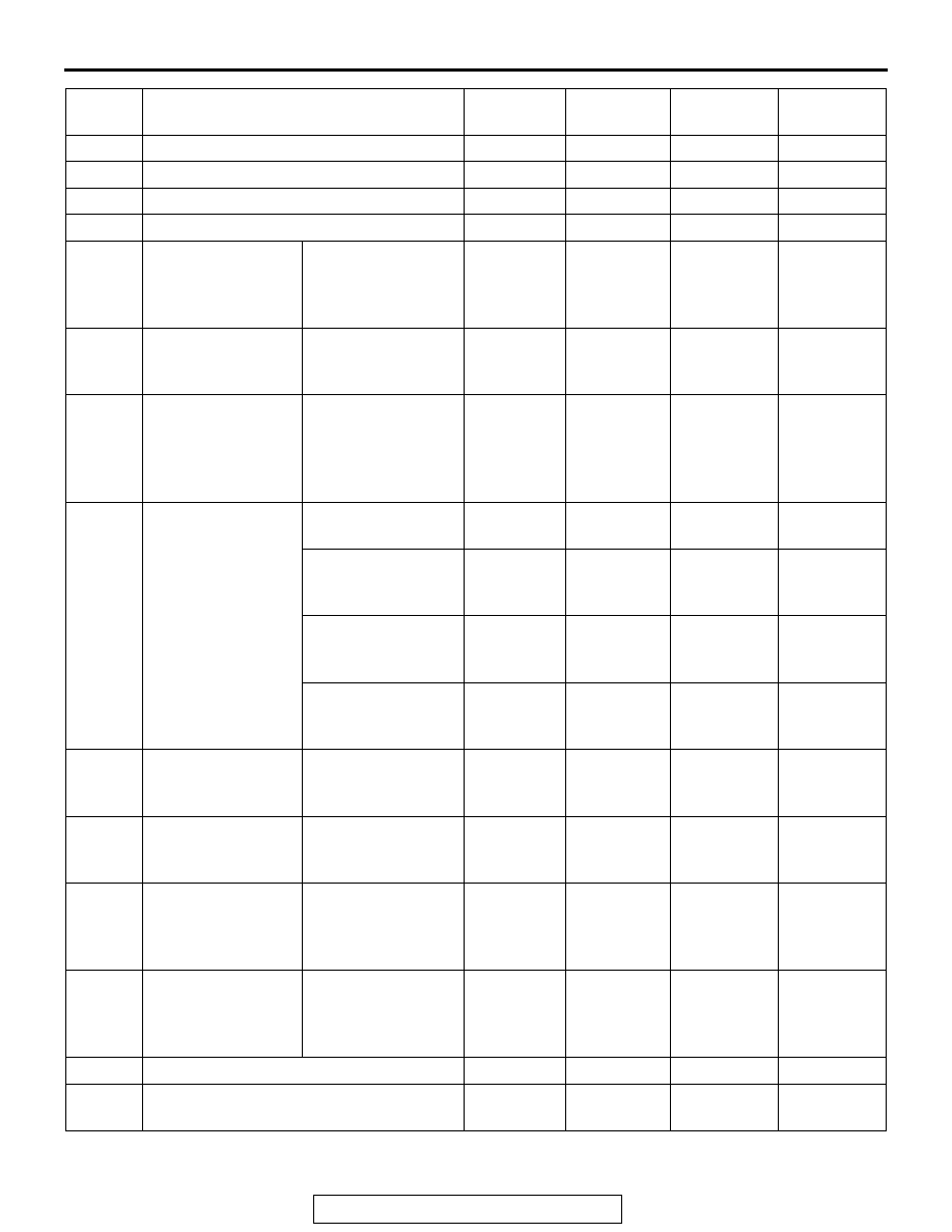
C121C
Torque request signal rejection
Executed
Executed
Prohibited
Prohibited
C1290
CAN time-out error
Executed
Executed
Prohibited
Prohibited
C2203
VIN not recorded
Executed
Executed
Executed
Executed
C2206
Re-execution of variant coding
Executed
Prohibited
Prohibited
Prohibited
C1210
Abnormality in G
and yaw rate
sensor
Abnormality in
longitudinal G
sensor output
voltage
Executed
Prohibited
Prohibited
Prohibited
C1242
Abnormality in G
and yaw rate
sensor
Abnormality in
longitudinal G
sensor output signal
Executed
Prohibited
Prohibited
Prohibited
C123C
Abnormality in G
and yaw rate
sensor
Abnormality in
lateral G and yaw
rate output value
(incorrect
installation)
Executed
Executed
Prohibited
Prohibited
C2204
Internal abnormality
in G and yaw rate
sensor
Communication
error
Executed
Prohibited
Prohibited
Prohibited
Abnormality in
lateral G sensor
output voltage
Executed
Executed
Prohibited
Prohibited
Abnormality in yaw
rate sensor output
voltage
Executed
Executed
Prohibited
Prohibited
Abnormality in G
and yaw rate sensor
supply voltage
Executed
Prohibited
Prohibited
Prohibited
C2111
Brake fluid
pressure sensor
power supply circuit
Low input
Executed
Prohibited
Prohibited
Prohibited
C2112
Brake fluid
pressure sensor
power supply circuit
High input
Executed
Prohibited
Prohibited
Prohibited
C2114
*4
Abnormality in G
and yaw rate
sensor operation
voltage
Low voltage (6.5 ±
0.5 V or less)
Executed
Prohibited
Prohibited
Prohibited
C2115
Abnormality in G
and yaw rate
sensor operation
voltage
High voltage (18.0 ±
1.0 V or more)
Executed
Prohibited
Prohibited
Prohibited
C123A
Abnormality in sensor calibration
Executed
Prohibited
Prohibited
Prohibited
C1219
Abnormality in steering wheel sensor
signal
Executed
Executed
Prohibited
Prohibited
DTC No. Item
EBD
ABS
Stability
control
TCL