Mitsubishi Lancer Evolution X. Manual - part 113
CRUISE CONTROL
TSB Revision
ENGINE AND EMISSION CONTROL
17-39
SYMPTOM PROCEDURES
Inspection Procedure 1: When the Brake Pedal is Depressed, Cruise Control is not Cancelled.
.
COMMENT
• Malfunction of CAN bus line.
• The stoplight switch circuit is suspected.
.
TROUBLESHOOTING HINTS (THE MOST
LIKELY CAUSES FOR THIS CASE:)
• Malfunction of CAN bus system.
• Damaged harness or connector.
• Malfunction of the stoplight switch.
• Malfunction of the ETACS-ECU.
• Malfunction of the ECM.
DIAGNOSTIC PROCEDURE
Required Special Tools:
• MB991958: Scan Tool (M.U.T.-III Sub Assembly)
• MB991824: V.C.I.
• MB991827: M.U.T.-III USB Cable
• MB991910: M.U.T.-III Main Harness A
CAUTION
If there is any problem in the CAN bus lines, an incorrect
diagnostic trouble code (DTC) may be set. Prior to this
diagnosis, diagnose the CAN bus lines (Refer to GROUP
54C, Trouble code diagnosis
STEP 1. Using scan tool MB991958, diagnose the CAN bus
line.
CAUTION
To prevent damage to scan tool MB991958, always turn the
ignition switch to the "LOCK" (OFF) position before con-
necting or disconnecting scan tool MB991958.
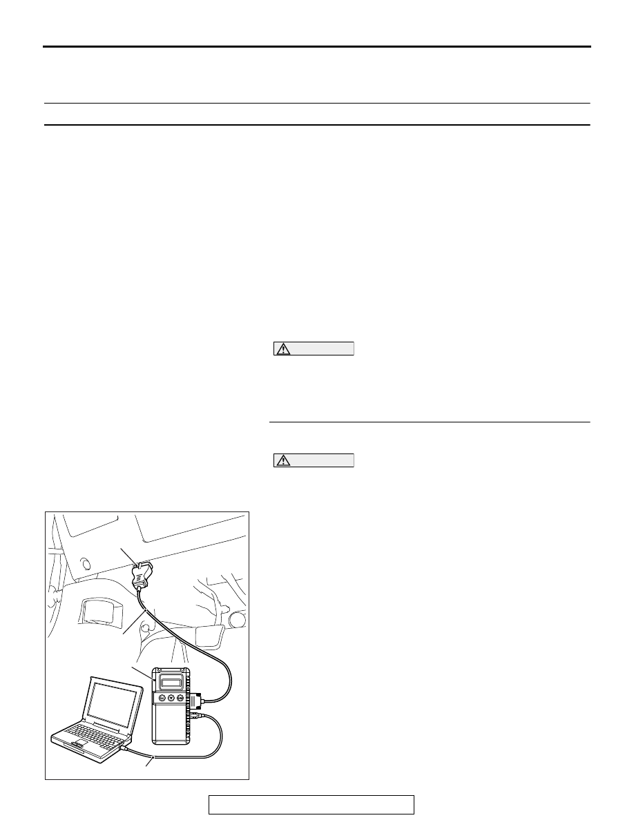
(1) Connect scan tool MB991958 to the data link connector
(Refer to
.)
(2) Turn the ignition switch to the "ON" position.
(3) Diagnose the CAN bus line (Refer to
Q: Is the check result satisfactory?
YES : Go to Step 2
NO : Repair the CAN bus lines (Refer to GROUP 54C,
Diagnosis − Can Bus Diagnostic Chart
Then go to Step 4.
AC608435
Data link connector
MB991827
MB991824
MB991910
AB