Mitsubishi Lancer Evolution X. Manual - part 96


  Index      Mitsubishi     Mitsubishi Lancer Evolution X GS41EVO - service repair manual 2008 year


Search            


Content   ..  94  95  96  97   ..


Mitsubishi Lancer Evolution X. Manual - part 96


CHARGING SYSTEM

TSB Revision

ENGINE ELECTRICAL

16-15

REMOVAL SERVICE POINTS

.

<<A>> A/C COMPRESSOR AND CLUTCH ASSEM-
BLY REMOVAL

1. With the hose installed, remove the A/C compressor and 

clutch assembly from the bracket.

2. Tie the removed A/C compressor and clutch assembly with 

a string at a position where it will not interfere with the 
removal and installation of the generator assembly.

.

<<B>> GENERATOR ASSEMBLY REMOVAL

Pull out the generator assembly upward.

INSTALLATION SERVICE POINT

.

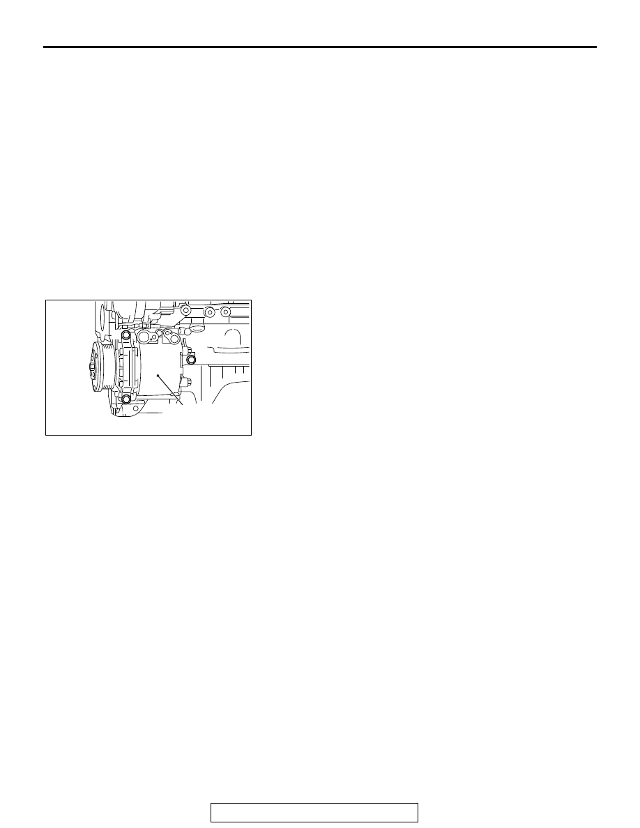
>>A<< A/C COMPRESSOR AND CLUTCH ASSEM-
BLY INSTALLATION

Tighten A/C compressor and clutch assembly mounting bolts to 
the specified torque in the order of number shown in the illus-
tration.

Tightening torque: 23 ± 6 N⋅ m (17 ± 4 ft-lb)

AC506759

AE

1

2

3

A/C compressor 
and clutch assembly

CHARGING SYSTEM

TSB Revision

ENGINE ELECTRICAL

16-16

DISASSEMBLY AND ASSEMBLY

M1161001600519

Required Special Tool:

• MB992226: Serration Socket

AK703147

1

3

4

5

6

7

8

9

10 11

12

13

14

16

3.9 ± 1.0 N·m
31 ± 12 in-lb

4.4 ± 1.0 N·m
39 ± 8 in-lb

AC

16 ± 2 N·m
12 ± 1 in-lb

73 ± 12 N·m
54 ± 8 ft-lb

2

15

2.0 ± 0.5 N·m
18 ± 4 in-lb

3.9 ± 1.0 N·m
31 ± 12 in-lb

2.0 ± 0.5 N·m
18 ± 4 in-lb

disassembly steps 

1. Cap

<<

A

>> >>

C

<< 2. Pulley

<<

B

>> >>

B

<< 3. Front bracket

4. Plate
5. Front bearing
6. Rotor
7. Rear bearing

<<

C

>>

8. Stator

9. Condenser assembly

<<

C

>> >>

A

<< 10. Regulator assembly

11. Brush
12. Rubber packing
13. Rectifier
14. Insulator
15. Bushing
16. Rear bracket

disassembly steps (Continued)

CHARGING SYSTEM

TSB Revision

ENGINE ELECTRICAL

16-17

DISASSEMBLY SERVICE POINTS

.

<<A>> PULLEY REMOVAL

1. Set the special tool MB992226 to the pulley.

2. Set the closed wrench to the hexagonal area of the special 

tool MB992226.

3. Insert the hexagonal bit socket having width across flats of 

10 mm into the hexagonal area of the rotor shaft.

4. Hold the pulley with the closed wrench. Rotate the rotor 

shaft clockwise to remove the pulley.

.

<<B>> FRONT BRACKET REMOVAL

CAUTION

Do not insert the screwdriver blades too deep. Doing so 
could damage the stator coil.
Insert the blades of screwdrivers between the front bracket and 
stator core, and pry and separate them with the screwdrivers.

.

AK602611AD

MB992226

AK602612 AD

MB992226

AK602614

MB992226

AD

AK703439

CHARGING SYSTEM

TSB Revision

ENGINE ELECTRICAL

16-18

<<C>> STATOR / REGULATOR ASSEMBLY 
REMOVAL

1. Remove 6 installation screws of the stator lead wire, and 

then remove the stator.

2. Remove 4 installation screws of the regulator to remove the 

regulator assembly.

REASSEMBLY SERVICE POINTS

.

>>A<< REGULATOR ASSEMBLY INSTALLATION

After installing the regulator assembly, insert a piece of wire 
through the hole in the rear bracket while pressing the brush to 
keep the brush against movement.
NOTE: Unless inserting the wire to fix the brush, the rotor 
installation is difficult.

.

AK703435AC

Regulator
assembly

Stator 
mounting 
screw

Rectifier 
assembly

Stator

Stator 
mounting 
screw

Regulator
mounting screw

AK703366AD

AK703434AC

Rear bracket

Brush

Wire


Content   ..  94  95  96  97   ..