Mitsubishi Lancer Evolution X. Manual - part 21
DIAGNOSIS
TSB Revision
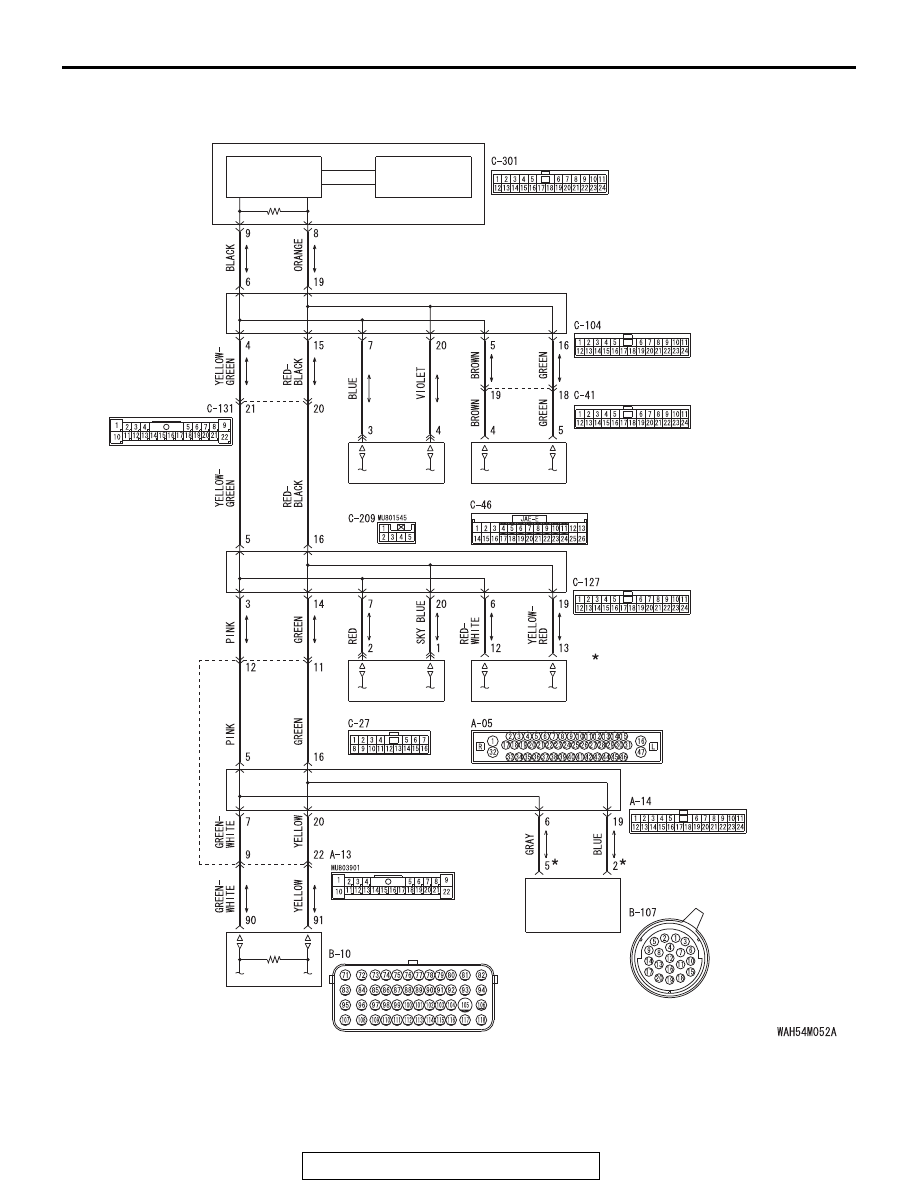
CONTROLLER AREA NETWORK (CAN)
54C-109
TRANSAXLE
ASSEMBLY
ENGINE CONTROL MODULE
CAN-C Communication Circuit <TC-SST>
ETACS-ECU
INTERFACE
CIRCUIT
CAN DRIVE
CIRCUIT
JOINT CONNECTOR
(CAN2)
JOINT CONNECTOR
(CAN3)
JOINT CONNECTOR
(CAN4)
SHIFT LEVER
ASC-ECU
STEERING
WHEEL SENSOR
AWC-ECU
NOTE
: THE TERMINAL NUMBERS DESCRIBED
IN THE CIRCUIT DIAGRAM AGREE WITH
THE NUMBERS MARKED ON THE
TRANSAXLE ASSEMBLY CONNECTOR AND
HARNESS SIDE CONNECTOR.