Mitsubishi Lancer Evolution X. Manual - part 14


  Index      Mitsubishi     Mitsubishi Lancer Evolution X GS41EVO - service repair manual 2008 year


Search            


Content   ..  12  13  14  15   ..


Mitsubishi Lancer Evolution X. Manual - part 14


DIAGNOSIS

TSB Revision

CONTROLLER AREA NETWORK (CAN)

54C-81

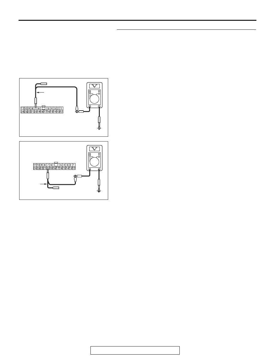
STEP 6. Check the wiring harness between joint connector 
(CAN3) C-127 and shift lever connector C-27 for a short to 
power supply. Measure the voltage at joint connector 
(CAN3) C-127.
(1) Disconnect joint connector (CAN3), and measure the 

voltage at the wiring harness side of joint connector 
(CAN3).

(2) Turn the ignition switch to the ON position.
(3) Measure the voltage between joint connector (CAN3) 

terminal 7 and body ground.

OK: 4.7 V or less

(4) Measure the voltage between joint connector (CAN3) 

terminal 20 and body ground.

OK: 4.7 V or less

Q: Do all the voltages measure 4.7 V or less?

YES : Go to Step 7.
NO :  Go to Step 15.

AC709708

TEST 
HARNESS

Harness side: C-127

AN

AC709708

Harness side: C-127

AO

TEST 
HARNESS

DIAGNOSIS

TSB Revision

CONTROLLER AREA NETWORK (CAN)

54C-82

STEP 7. Check the wiring harness between joint connector 
(CAN4) A-14 and ECM connector B-10 <TC-SST> for a 
short to power supply. Measure the voltage at joint 
connector (CAN4) A-14.
(1) Disconnect joint connector (CAN4), and measure the 

voltage at the wiring harness side of joint connector 
(CAN4).

(2) Turn the ignition switch to the ON position.
(3) Measure the voltage between joint connector (CAN4) 

terminal 7 and body ground.

OK: 4.7 V or less

(4) Measure the voltage between joint connector (CAN4) 

terminal 20 and body ground.

OK: 4.7 V or less

Q: Do all the voltages measure 4.7 V or less?

YES : Go to Step 8.
NO :  Go to Step 14.

AC709708

TEST 
HARNESS

Harness side: A-14

AP

AC709708

Harness side: A-14

AQ

TEST 
HARNESS

DIAGNOSIS

TSB Revision

CONTROLLER AREA NETWORK (CAN)

54C-83

STEP 8. Check the wiring harness between joint connector 
(CAN4) A-14 and transaxle assembly connector B-107 for a 
short to power supply. Measure the voltage at joint 
connector (CAN4) A-14.
(1) Disconnect joint connector (CAN4), and measure the 

voltage at the wiring harness side of joint connector 
(CAN4).

(2) Turn the ignition switch to the ON position.
(3) Measure the voltage between joint connector (CAN4) 

terminal 6 and body ground.

OK: 4.7 V or less

(4) Measure the voltage between joint connector (CAN4) 

terminal 19 and body ground.

OK: 4.7 V or less

Q: Do all the voltages measure 4.7 V or less?

YES : Go to Step 9.
NO :  Go to Step 16.

AC709708

TEST 
HARNESS

Harness side: A-14

AR

AC709708

Harness side: A-14

AS

TEST 
HARNESS

DIAGNOSIS

TSB Revision

CONTROLLER AREA NETWORK (CAN)

54C-84

STEP 9. Check the wiring harness between joint connector 
(CAN3) C-127 and joint connector (CAN2) C-104 for a short 
to ground. Measure the resistance at joint connector 
(CAN3) C-127.

CAUTION

Disconnect the negative battery terminal. For details refer 
to 

P.54C-7

.

CAUTION

A digital multimeter should be used. For details refer to 

P.54C-7

.

CAUTION

The test wiring harness should be used. For details refer to 

P.54C-7

.

(1) Disconnect joint connector (CAN3), and measure the 

resistance at the wiring harness side of joint connector 
(CAN3).

(2) Turn the ignition switch to the ON position.
(3) Measure the voltage between joint connector (CAN3) 

terminal 5 and body ground.

OK: 4.7 V or less

(4) Measure the voltage between joint connector (CAN3) 

terminal 16 and body ground.

OK: 4.7 V or less

Q: Do all the voltages measure 4.7 V or less?

YES : Check intermediate connector A-13, and repair if 

necessary. If the intermediate connector is in good 
condition, repair the wiring harness between joint 
connector (CAN3) C-127 and joint connector (CAN4) 
A-14.

NO :  Check intermediate connector C-131, and repair if 

necessary. If the intermediate connector is in good 
condition, repair the wiring harness between joint 
connector (CAN3) C-127 and joint connector (CAN2) 
C-104.

AC709708

TEST 
HARNESS

Harness side: C-127

AT

AC709708

Harness side: C-127

AU

TEST 
HARNESS


Content   ..  12  13  14  15   ..