Mitsubishi Lancer Evolution X. Manual - part 9


  Index      Mitsubishi     Mitsubishi Lancer Evolution X GS41EVO - service repair manual 2008 year


Search            


Content   ..  7  8  9  10   ..


Mitsubishi Lancer Evolution X. Manual - part 9


DIAGNOSIS

TSB Revision

CONTROLLER AREA NETWORK (CAN)

54C-61

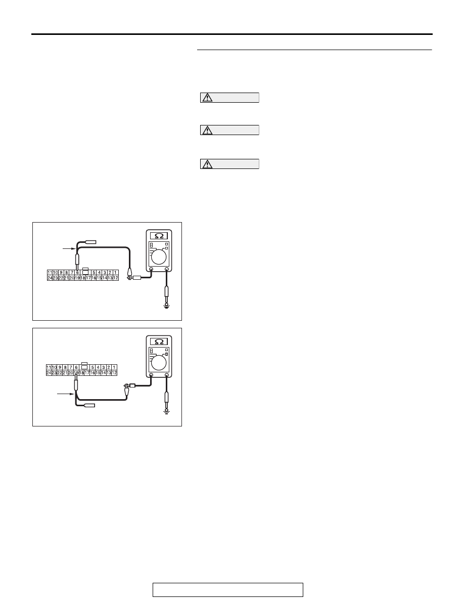
STEP 8. Check the wiring harness between joint connector 
(CAN4) A-14 and transaxle assembly connector B-107 
<TC-SST> for a short to ground. Measure the resistance at 
joint connector (CAN4) A-14.

CAUTION

Disconnect the negative battery terminal. For details refer 
to 

P.54C-7

.

CAUTION

A digital multimeter should be used. For details refer to 

P.54C-7

.

CAUTION

The test wiring harness should be used. For details refer to 

P.54C-7

.

(1) Disconnect joint connector (CAN4), and measure the 

resistance at the wiring harness side of joint connector 
(CAN4).

(2) Measure the resistance between joint connector (CAN4) 

terminal 6 and body ground.

OK: 1 kΩ or more

(3) Measure the resistance between joint connector (CAN4) 

terminal 19 and body ground.

OK: 1 kΩ or more

Q: Do all the resistances measure 1 kΩ or more?

YES : Go to Step 9.
NO :  Go to Step 16.

AC709707

TEST 
HARNESS

Harness side: A-14

BD

AC709707BE

TEST 
HARNESS

Harness side: A-14

DIAGNOSIS

TSB Revision

CONTROLLER AREA NETWORK (CAN)

54C-62

STEP 9. Check the wiring harness between joint connector 
(CAN3) C-127 and joint connector (CAN2) C-104 for a short 
to ground. Measure the resistance at joint connector 
(CAN3) C-127.

CAUTION

Disconnect the negative battery terminal. For details refer 
to 

P.54C-7

.

CAUTION

A digital multimeter should be used. For details refer to 

P.54C-7

.

CAUTION

The test wiring harness should be used. For details refer to 

P.54C-7

.

(1) Disconnect joint connector (CAN3), and measure the 

resistance at the wiring harness side of joint connector 
(CAN3).

(2) Measure the resistance between joint connector (CAN3) 

terminal 5 and body ground.

OK: 1 kΩ or more

(3) Measure the resistance between joint connector (CAN3) 

terminal 16 and body ground.

OK: 1 kΩ or more

Q: Do all the resistances measure 1 kΩ or more?

YES : Check intermediate connector A-13, and repair if 

necessary. If the intermediate connector is in good 
condition, repair the wiring harness between joint 
connector (CAN3) C-127 and joint connector (CAN4) 
A-14.

NO :  Check intermediate connector C-131, and repair if 

necessary. If the intermediate connector is in good 
condition, repair the wiring harness between joint 
connector (CAN3) C-127 and joint connector (CAN2) 
C-104.

AC709707

TEST 
HARNESS

Harness side: C-127

BF

AC709707BG

TEST 
HARNESS

Harness side: C-127

DIAGNOSIS

TSB Revision

CONTROLLER AREA NETWORK (CAN)

54C-63

STEP 10. Using scan tool MB991958, diagnose the CAN 
bus line. (checking the steering wheel sensor for internal 
short to ground)

CAUTION

Strictly observe the specified wiring harness repair proce-
dure. For details refer to 

P.54C-7

.

CAUTION

To prevent damage to scan tool MB991958, always turn the 
ignition switch to the "LOCK" (OFF) position before con-
necting or disconnecting scan tool MB991958.
(1) Disconnect steering wheel sensor connector C-209.
(2) Connect scan tool MB991958 to the data link connector.
(3) Turn the ignition switch to the "ON" position.

AC608435

Data link connector

MB991827

MB991824

MB991910

AB

DIAGNOSIS

TSB Revision

CONTROLLER AREA NETWORK (CAN)

54C-64

(4) Diagnose CAN bus lines, and check if the scan tool 

MB991958 screen is as shown in the figure.

OK: The display of the scan tool MB991958 is as 
shown in the figure.

Q: Does scan tool MB991958 screen correspond to the 

illustration?
YES : 
Repair the wiring harness between steering wheel 

sensor connector C-209 and joint connector (CAN2) 
C-104.

NO :  Check steering wheel sensor connector C-209, and 

repair if necessary. If the steering wheel sensor 
connector is in good condition, replace the steering 
wheel sensor.

AC709542 AC

: Red section on screen

M.U.T.

J/C (3)

J/C (2)

KOS/WCM

SRS

A/C

AUDIO

MMCS

Sat Radio

HFM

OCM

METER

ASC

ENGINE

J/C (1)

ETACS

<M/T>

SAS

S-AWC

AC709543 AC

: Red section on screen

M.U.T.

J/C (3)

J/C (2)

KOS/WCM

SRS

A/C

AUDIO

MMCS

Sat Radio

HFM

OCM

METER

ASC

LEVER

J/C (1)

ETACS

<TC-SST>

SAS

S-AWC

J/C (4)

TC-SST

ENGINE


Content   ..  7  8  9  10   ..