Mitsubishi Lancer Evolution IX. Manual - part 637
TROUBLESHOOTING
SUPPLEMENTAL RESTRAINT SYSTEM (SRS)
52B-61
OPERATION
• Power for the SRS warning lamp is supplied from
the ignition switch (IG1) circuit.
• The SRS warning lamp illuminates when the igni-
tion switch is turned to the "ON" position and
goes out after approximately 7 seconds if there is
not a malfunction in the SRS system.
DIAGNOSIS CODE SET CONDITIONS
• This diagnosis code is set when an open circuit is
detected for a continuous period of 5 seconds
while the SRS-ECU is monitoring the SRS warn-
ing lamp and the lamp is OFF. (transistor OFF).
However, if the vehicle condition returns to nor-
mal, diagnosis code 43 will be automatically
erased, and the SRS warning lamp will go out.
PROBABLE CAUSES
• Damaged wiring harnesses of connectors
• Blown bulb
• Malfunction of the SRS-ECU
• Malfunction of the combination meter
DIAGNOSIS PROCEDURE
STEP 1. Check the SRS warning lamp.
(1) Disconnect the negative battery terminal.
(2) Disconnected the SRS-ECU connector C-12.
(3) Connect the negative battery terminal.
(4) Turn the ignition switch to the "ON" position.
Q: Does the warning lamp illuminate?
YES :
Go to Step 4.
NO :
Go to Step 2.
STEP 2. Check the SRS warning lamp bulb.
Q: Has the SRS warning lamp bulb blown?
YES :
Replace the SRS warning lamp bulb.
NO :
Go to Step 3.
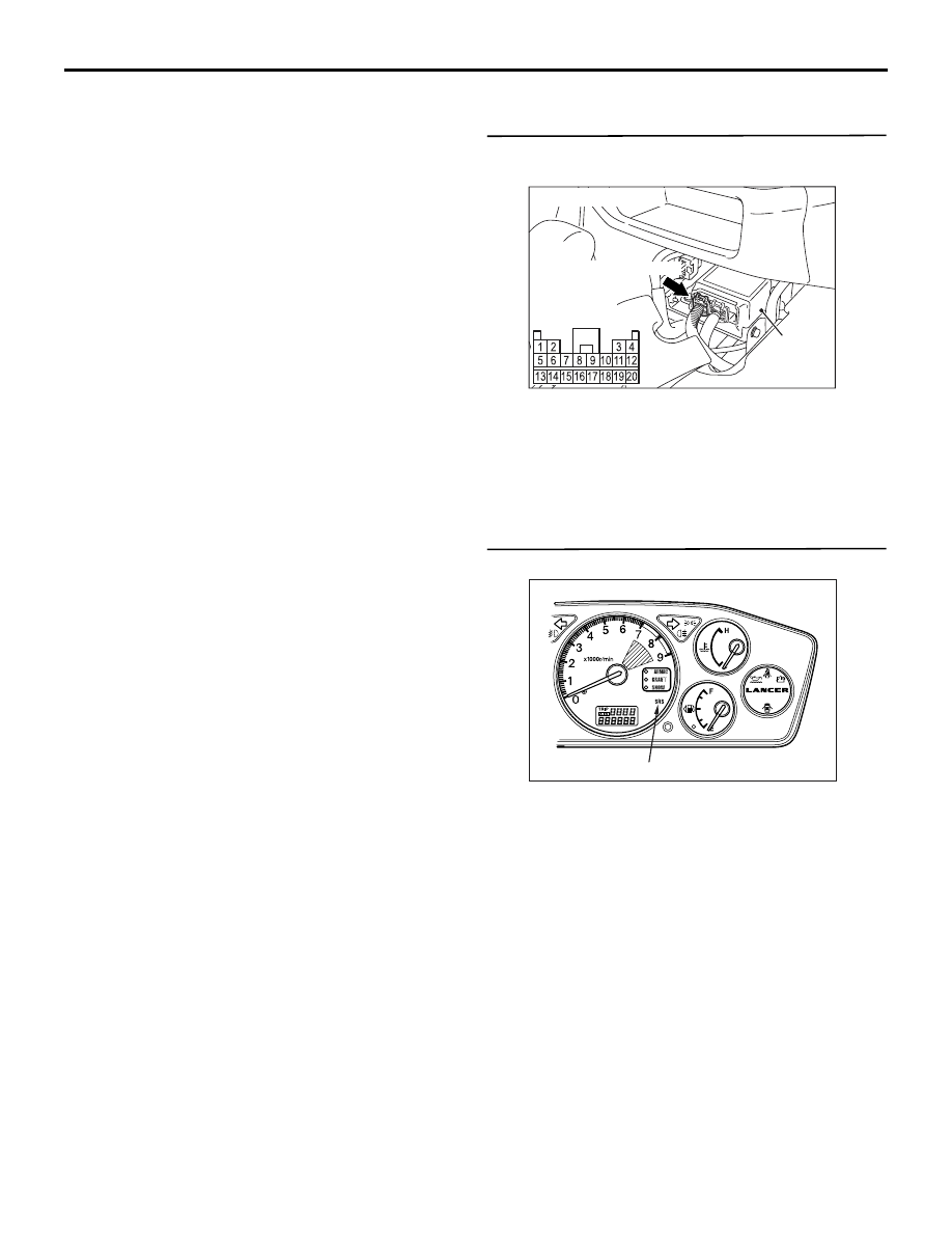
AC101950AJ
SRS-ECU
Harness side
connector
(rear view)
C-12 (Y)
Connector: C-12
AC311044
SRS warning lamp
AB