Mitsubishi Lancer Evolution IX. Manual - part 564
 

  Index      Mitsubishi     Mitsubishi Lancer Evolution IX - service repair manual


Search            


Content   ..  562  563  564  565   ..


Mitsubishi Lancer Evolution IX. Manual - part 564


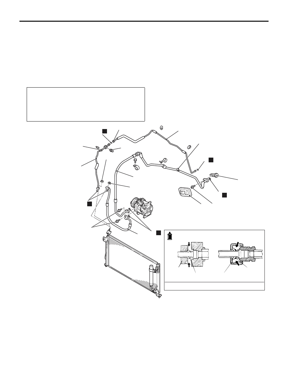
REFRIGERANT LINE

HEATER, AIR CONDITIONER AND VENTILATION

55-129

INSTALLATION SERVICE POINT
>>A<< FLEXIBLE SUCTION HOSE 
INSTALLATION

When replacing the suction hose, refill them with a 
specified amount of compressor oil, and then install 
them.

Compressor oil: SUN PAG 56
Quantity: Suction hose: 10 cm

3

REMOVAL AND INSTALLATION <RHD>

M1552006401074

Pre-removal and Post-installation Operation
• Refrigerant Draining and Refilling (Refer to 

P.55-104

).

• Air Cleaner Removal and Installation (Refer to GROUP 

15, Air cleaner 

P.15-5

).

• Radiator Grille Removal and Installation (Refer to 

GROUP 51, Front bumper 

P.51-2

).

AC304554

1

2

3

4

5

6

7

8

N

8

N

8

N

N

8

8

N

4.9 ± 0.9 N·m

Low-pressure side 
service valve 

13 ± 1 N·m

High-pressure
Side Service Valve 

25 ± 4 N·m

12 ± 2 N·m

AB

6

A/C compressor oil: SUN PAG 56

-Pipe coupling

O-ring

O-ring

1, 2, 3,
5, 6

12 ± 2 N·m

Removal steps 

<<

A

>>

1.

Dual pressure switch

<<

A

>>

2.

Liquid pipe A

<<

A

>>

3.

Flexible discharge hose

4.

Expansion valve cover

<<

A

>>

>>

A

<<

5.

Flexible suction hose

<<

A

>>

6.

Liquid pipe B

7.

Expansion valve cover

8.

O-ring

Removal steps (Continued)

DUCTS

HEATER, AIR CONDITIONER AND VENTILATION

55-130

REMOVAL SERVICE POINT
<<A>> HOSE/PIPE DISCONNECTION

CAUTION

As the compressor oil and receiver are highly 
moisture absorbent, use a non-porous material 
to plug the hose and nipples.
To prevent the entry of other foreign bodies, plug the 
condenser, compressor, and expansion valve nip-
ples.

INSTALLATION SERVICE POINT
>>A<< FLEXIBLE SUCTION HOSE 
INSTALLATION

When replacing the suction hose, refill them with a 
specified amount of compressor oil, and then install 
them.

Compressor oil: SUN PAG 56
Quantity: Suction hose: 10 cm

3

DUCTS

REMOVAL AND INSTALLATION

M1553001000134

AC304890

7

8

13

12

11

10

9

3

6

4

5

4

3

2

1

AB

A

A

Clip

Instrument panel

1

Cross-section A-A

Air Outlet Removal steps 

1.

Centre Air Outlet Panel

2.

Centre Air Outlet

3.

Side Air Outlet

Defroster nozzle and Distribution 
duct Removal steps 

•

Instrument Panel (Refer to 52A, 
Instrument Panel 

P.52A-2

).

4.

Side defroster duct

VENTILATORS

HEATER, AIR CONDITIONER AND VENTILATION

55-131

VENTILATORS

REMOVAL AND INSTALLATION

M1553001600523

5.

Defroster nozzle

6.

Distribution duct
Foot duct Removal steps 

•

Console cover and Glove box 
(Refer to GROUP 52A, Instrument 
panel 

P.52A-2

).

7.

Foot duct (RH)

8.

Rear heater duct A (RH) upper side

•

Under cover (Refer to GROUP 
52A, Instrument panel 

P.52A-2

).

Defroster nozzle and Distribution 
duct Removal steps (Continued)

9.

Foot duct (LH)
Rear heater duct Removal steps 

•

Front floor console (Refer to 
GROUP 52A, Front floor console 
assembly 

P.52A-7

).

•

Front seat (Refer to GROUP 52A - 
Front seat assembly 

P.52A-18

).

•

Floor carpet and Floor pads 

10. Rear heater duct A (LH)
11. Left -hand rear heater duct B
12. Right-hand rear heater duct B
13. Rear heater duct A (RH) lower side

Foot duct Removal steps 

AC211528

Cross-Section A –


A

1

Claw

Cross-Section B –


B

1

Claw

B

B

A

A

A

A

AD

1

Rear ventilation duct removal 
steps 

•

Rear bumper assembly (Refer to 
GROUP 51, Rear bumper 

P.51-5

).

1.

Rear ventilation duct

NOTES


Content   ..  562  563  564  565   ..